How to Use 4 RELAY MODULE: Examples, Pinouts, and Specs
Introduction
A 4 relay module is an electronic component that allows control of multiple devices using a single microcontroller or switch. It typically consists of four relays that can be activated independently, enabling the switching of high voltage or high current loads safely.
This module is widely used in home automation, industrial control systems, and robotics. It provides an efficient way to control high-power devices such as lights, fans, motors, and other appliances using low-power control signals from microcontrollers like Arduino, Raspberry Pi, or other logic circuits.
Explore Projects Built with 4 RELAY MODULE


Explore Projects Built with 4 RELAY MODULE
Technical Specifications
Below are the key technical details of a standard 4 relay module:
- Operating Voltage: 5V DC (common) or 12V DC (varies by model)
- Trigger Voltage: 3.3V to 5V (compatible with most microcontrollers)
- Relay Type: Electromechanical
- Maximum Load (per relay):
- AC: 250V at 10A
- DC: 30V at 10A
- Isolation: Optocoupler isolation for safe operation
- Indicator LEDs: One LED per relay to indicate activation
- Dimensions: Typically 75mm x 55mm x 20mm (varies by manufacturer)
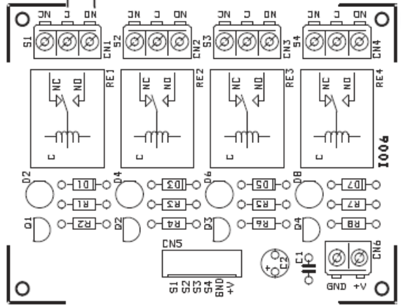
Pin Configuration and Descriptions
The 4 relay module typically has the following pin configuration:
Input Pins
| Pin Name | Description |
|---|---|
| VCC | Power supply input (5V DC or 12V DC depending on the module version). |
| GND | Ground connection. |
| IN1 | Control signal for Relay 1 (active LOW or HIGH depending on module design). |
| IN2 | Control signal for Relay 2 (active LOW or HIGH depending on module design). |
| IN3 | Control signal for Relay 3 (active LOW or HIGH depending on module design). |
| IN4 | Control signal for Relay 4 (active LOW or HIGH depending on module design). |
Output Terminals (Relay Contacts)
Each relay has three output terminals:
| Terminal Name | Description |
|---|---|
| NO (Normally Open) | Open circuit when the relay is inactive; closed when the relay is active. |
| NC (Normally Closed) | Closed circuit when the relay is inactive; open when the relay is active. |
| COM (Common) | Common terminal for the relay. Connects to either NO or NC depending on state. |
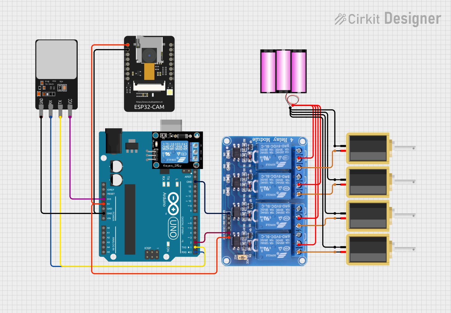
Usage Instructions
How to Use the 4 Relay Module in a Circuit
- Power the Module: Connect the VCC pin to a 5V DC power source and the GND pin to ground.
- Connect Control Signals: Connect the IN1, IN2, IN3, and IN4 pins to the digital output pins of a microcontroller (e.g., Arduino).
- Connect the Load:
- Identify the device you want to control (e.g., a light bulb or motor).
- Connect one terminal of the device to the relay's COM terminal.
- Connect the other terminal of the device to either the NO or NC terminal, depending on whether you want the device to be ON or OFF by default.
- Write Control Code: Use the microcontroller to send HIGH or LOW signals to the IN pins to activate or deactivate the relays.
Important Considerations and Best Practices
- Isolation: Ensure the module's optocoupler isolation is intact to protect the microcontroller from high voltage spikes.
- Power Supply: Use a stable power supply to avoid erratic relay behavior.
- Load Ratings: Do not exceed the relay's maximum load ratings to prevent damage.
- Flyback Diodes: If controlling inductive loads (e.g., motors), use flyback diodes to suppress voltage spikes.
- Active LOW vs. HIGH: Check the module's datasheet to confirm whether the relays are triggered by LOW or HIGH signals.
Example Code for Arduino UNO
Below is an example code snippet to control a 4 relay module using an Arduino UNO:
// Define relay control pins
#define RELAY1 2  // Pin connected to IN1
#define RELAY2 3  // Pin connected to IN2
#define RELAY3 4  // Pin connected to IN3
#define RELAY4 5  // Pin connected to IN4

void setup() {
  // Set relay pins as outputs
  pinMode(RELAY1, OUTPUT);
  pinMode(RELAY2, OUTPUT);
  pinMode(RELAY3, OUTPUT);
  pinMode(RELAY4, OUTPUT);

  // Initialize all relays to OFF state
  digitalWrite(RELAY1, LOW);
  digitalWrite(RELAY2, LOW);
  digitalWrite(RELAY3, LOW);
  digitalWrite(RELAY4, LOW);
}

void loop() {
  // Example: Turn relays ON and OFF sequentially
  digitalWrite(RELAY1, HIGH); // Turn ON Relay 1
  delay(1000);                // Wait for 1 second
  digitalWrite(RELAY1, LOW);  // Turn OFF Relay 1

  digitalWrite(RELAY2, HIGH); // Turn ON Relay 2
  delay(1000);                // Wait for 1 second
  digitalWrite(RELAY2, LOW);  // Turn OFF Relay 2

  digitalWrite(RELAY3, HIGH); // Turn ON Relay 3
  delay(1000);                // Wait for 1 second
  digitalWrite(RELAY3, LOW);  // Turn OFF Relay 3

  digitalWrite(RELAY4, HIGH); // Turn ON Relay 4
  delay(1000);                // Wait for 1 second
  digitalWrite(RELAY4, LOW);  // Turn OFF Relay 4
}
Troubleshooting and FAQs
Common Issues
Relays Not Activating:
- Ensure the module is powered with the correct voltage (5V or 12V).
- Verify that the control signals from the microcontroller are within the required voltage range.
- Check for loose or incorrect wiring.
Erratic Relay Behavior:
- Use a stable power supply to avoid voltage fluctuations.
- Ensure proper grounding between the module and the microcontroller.
Load Not Switching:
- Confirm that the load is connected to the correct relay terminals (COM, NO, or NC).
- Verify that the load does not exceed the relay's maximum current and voltage ratings.
FAQs
Q1: Can I use the 4 relay module with a 3.3V microcontroller like ESP32?
A1: Yes, most 4 relay modules are compatible with 3.3V control signals. However, check the module's datasheet to confirm compatibility.
Q2: Is it safe to control AC appliances with this module?
A2: Yes, the module is designed for AC loads up to 250V at 10A. Ensure proper insulation and follow safety guidelines when working with high voltage.
Q3: Can I control all four relays simultaneously?
A3: Yes, you can activate all four relays at the same time, provided your power supply can handle the combined current draw.
Q4: Why are there LEDs on the module?
A4: The LEDs indicate the activation status of each relay, making it easier to debug and monitor the module's operation.