
How to Use 5v fan: Examples, Pinouts, and Specs
 Design with 5v fan in Cirkit Designer
Introduction
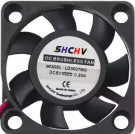
A 5V fan is a small electric fan designed to operate on a 5-volt DC power supply. It is commonly used for cooling electronic components, such as microcontrollers, processors, and power regulators, or for providing airflow in compact spaces like enclosures and small devices. Due to its low power consumption and compact size, the 5V fan is ideal for applications where space and energy efficiency are critical.
Explore Projects Built with 5v fan
 Open Project in Cirkit Designer
 Open Project in Cirkit Designer
 Open Project in Cirkit Designer
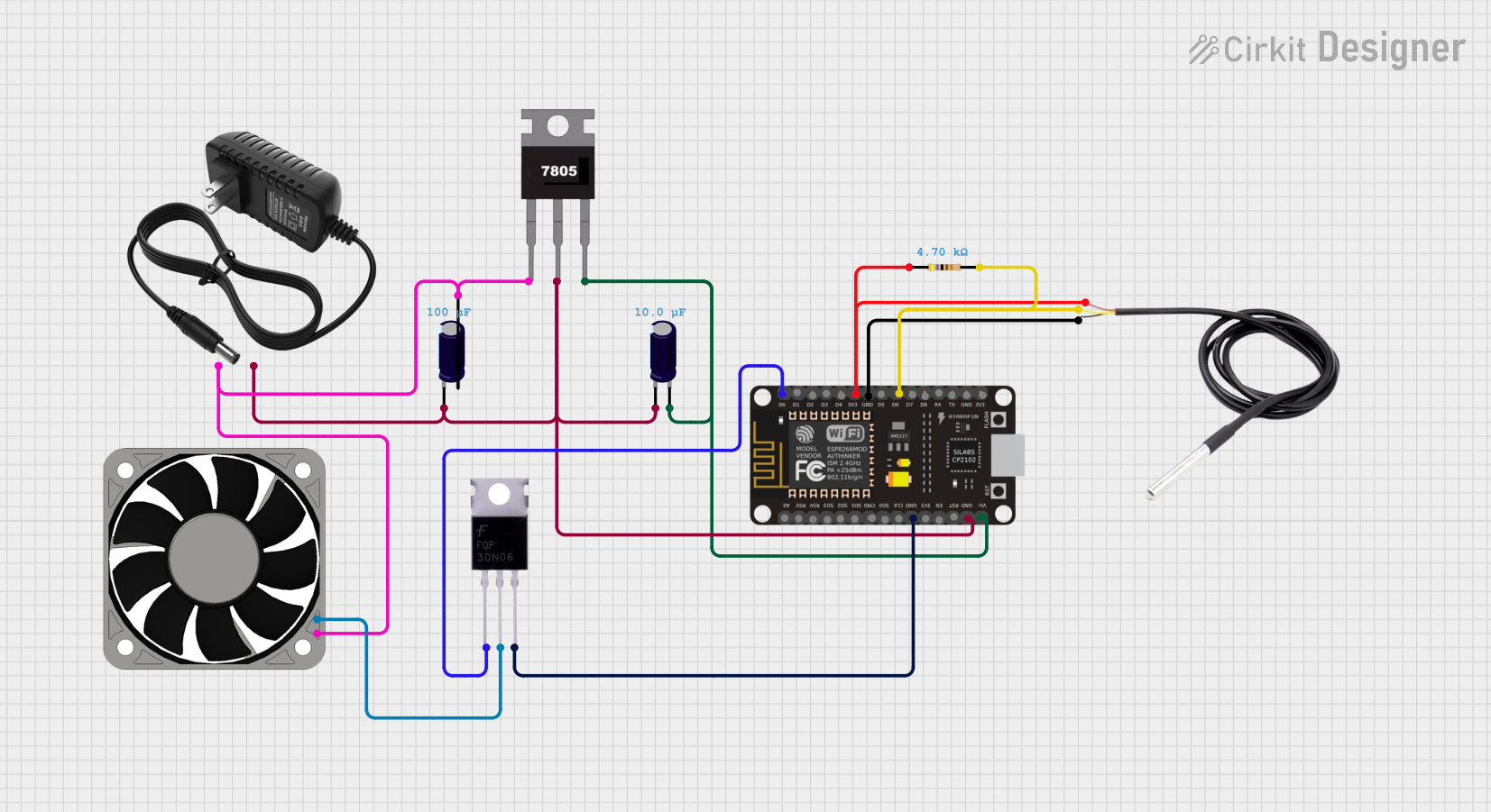 Open Project in Cirkit Designer
Explore Projects Built with 5v fan
Open Project in Cirkit DesignerOpen Project in Cirkit DesignerOpen Project in Cirkit DesignerOpen Project in Cirkit DesignerCommon Applications
- Cooling Raspberry Pi, Arduino, or other microcontroller boards
- Ventilation in small enclosures or cases
- Heat dissipation for power regulators or MOSFETs
- Compact cooling solutions for DIY electronics projects
Technical Specifications
Key Technical Details
| Parameter | Value |
|---|---|
| Operating Voltage | 5V DC |
| Operating Current | Typically 0.1A to 0.3A |
| Power Consumption | 0.5W to 1.5W |
| Fan Speed | 3000–8000 RPM (varies by model) |
| Airflow | 2–10 CFM (varies by model) |
| Noise Level | 20–30 dBA (varies by model) |
| Dimensions | Common sizes: 30x30mm, 40x40mm, 50x50mm |
| Connector Type | 2-pin or 3-pin JST or Dupont |
Pin Configuration
| Pin Number | Wire Color (Typical) | Description |
|---|---|---|
| 1 | Red | Positive terminal (VCC, +5V) |
| 2 | Black | Negative terminal (GND) |
| 3 (optional) | Yellow | Tachometer signal (RPM feedback, if available) |
Note: Not all 5V fans include a tachometer signal. For basic 2-pin fans, only the red and black wires are used.
Usage Instructions
How to Use the 5V Fan in a Circuit
- Power Connection: Connect the red wire of the fan to a 5V DC power source and the black wire to ground (GND). Ensure the power supply can provide sufficient current for the fan's operation.
- Optional Tachometer Signal: If the fan has a yellow wire, connect it to a microcontroller's input pin to monitor the fan's speed (RPM). This requires additional programming.
- Mounting: Secure the fan in place using screws or adhesive mounts. Ensure the airflow direction aligns with your cooling requirements (usually indicated by arrows on the fan housing).
Important Considerations
- Voltage Compatibility: Ensure the fan is powered by a stable 5V DC source. Overvoltage can damage the fan, while undervoltage may reduce performance.
- Current Requirements: Verify that your power supply can handle the fan's current draw, especially if multiple components share the same supply.
- Airflow Direction: Check the airflow direction (usually marked on the fan) to ensure proper cooling.
- Noise Levels: If noise is a concern, consider using a fan with a lower RPM or adding a fan speed controller.
Example: Connecting a 5V Fan to an Arduino UNO
The following example demonstrates how to control a 5V fan using an Arduino UNO and a transistor for switching.
Circuit Diagram
- Connect the fan's red wire to the collector of an NPN transistor (e.g., 2N2222).
- Connect the fan's black wire to GND.
- Connect the emitter of the transistor to GND.
- Connect a 1kΩ resistor between the Arduino's digital pin (e.g., pin 9) and the base of the transistor.
- Connect the Arduino's GND to the power supply's GND.
Arduino Code
// Define the pin connected to the transistor's base
const int fanPin = 9;

void setup() {
  pinMode(fanPin, OUTPUT); // Set the fan control pin as an output
}

void loop() {
  digitalWrite(fanPin, HIGH); // Turn the fan ON
  delay(5000);               // Keep the fan ON for 5 seconds
  digitalWrite(fanPin, LOW);  // Turn the fan OFF
  delay(5000);               // Keep the fan OFF for 5 seconds
}
Note: This example uses a transistor to switch the fan on and off. Directly connecting the fan to an Arduino pin is not recommended, as the fan's current draw may exceed the pin's maximum rating.
Troubleshooting and FAQs
Common Issues
Fan Does Not Spin
- Cause: Insufficient power supply or incorrect wiring.
- Solution: Verify the power supply voltage and current. Check the wiring connections.
Fan Spins Slowly
- Cause: Undervoltage or excessive load on the power supply.
- Solution: Ensure the power supply provides a stable 5V and sufficient current.
Fan is Noisy
- Cause: Dust buildup, misalignment, or high RPM.
- Solution: Clean the fan blades, ensure proper mounting, or use a fan with lower RPM.
Fan Overheats
- Cause: Prolonged operation at high ambient temperatures.
- Solution: Improve ventilation or reduce the fan's duty cycle.
FAQs
Can I power a 5V fan with a USB port? Yes, most USB ports provide 5V and sufficient current to power a small 5V fan. However, ensure the fan's current draw does not exceed the USB port's limit (typically 500mA for USB 2.0).
Can I control the fan speed? Yes, you can control the fan speed using PWM (Pulse Width Modulation) if your fan supports it or by using an external fan speed controller.
What is the lifespan of a 5V fan? The lifespan depends on the fan's quality and operating conditions but typically ranges from 20,000 to 50,000 hours.
Can I use a 5V fan with a 3.3V system? No, a 5V fan requires a 5V power supply for proper operation. Using a 3.3V system may result in insufficient performance or failure to operate.