
How to Use Prolight RGB 3 Watt Star: Examples, Pinouts, and Specs
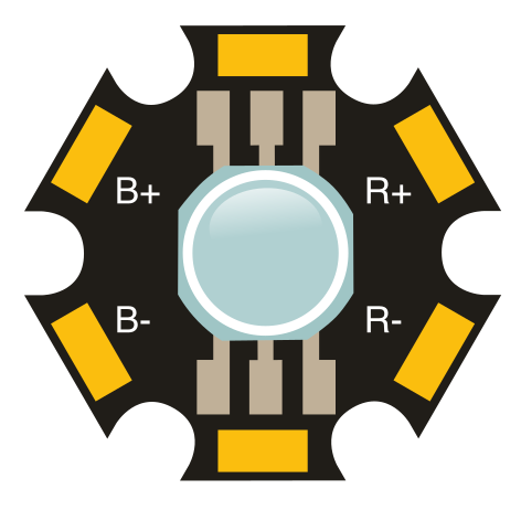
 Design with Prolight RGB 3 Watt Star in Cirkit Designer
Introduction
The Prolight RGB 3 Watt Star is a high-intensity LED light source that combines red, green, and blue (RGB) colors to produce a wide spectrum of colors. This versatile component is ideal for applications requiring dynamic lighting effects, such as stage lighting, architectural lighting, decorative installations, and DIY projects. Its compact design and high brightness make it a popular choice for both professional and hobbyist use.
Explore Projects Built with Prolight RGB 3 Watt Star
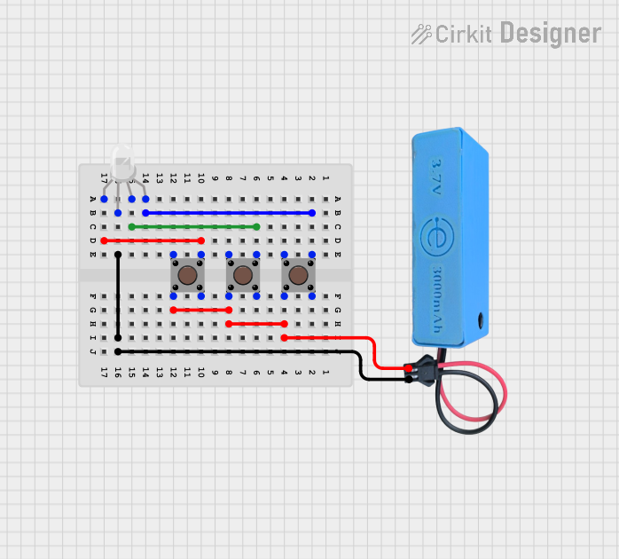 Open Project in Cirkit Designer
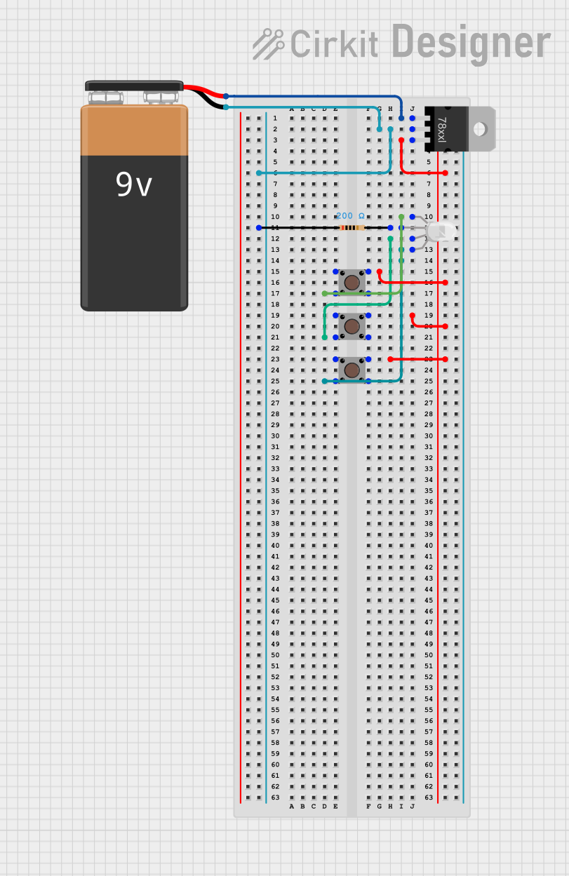 Open Project in Cirkit Designer
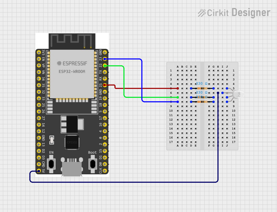 Open Project in Cirkit Designer
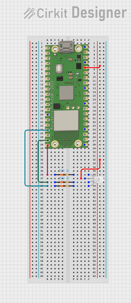 Open Project in Cirkit Designer
Explore Projects Built with Prolight RGB 3 Watt Star
Open Project in Cirkit DesignerOpen Project in Cirkit DesignerOpen Project in Cirkit DesignerOpen Project in Cirkit DesignerTechnical Specifications
The Prolight RGB 3 Watt Star is designed to deliver high performance while maintaining energy efficiency. Below are the key technical details:
General Specifications
| Parameter | Value |
|---|---|
| Power Consumption | 3 Watts (1 Watt per color) |
| Operating Voltage | Red: 2.0-2.6V, Green: 3.0-3.6V, Blue: 3.0-3.6V |
| Forward Current (Max) | 350mA per color |
| Wavelength Range | Red: 620-630nm, Green: 520-535nm, Blue: 460-475nm |
| Luminous Intensity | Red: 30-40lm, Green: 60-80lm, Blue: 15-25lm |
| Viewing Angle | 120° |
| Thermal Resistance | ≤10°C/W |
| Operating Temperature | -40°C to +85°C |
Pin Configuration and Descriptions
The Prolight RGB 3 Watt Star has four solder pads for electrical connections. The table below describes each pad:
| Pin Number | Label | Description |
|---|---|---|
| 1 | Red (+) | Positive terminal for the red LED |
| 2 | Green (+) | Positive terminal for the green LED |
| 3 | Blue (+) | Positive terminal for the blue LED |
| 4 | Common (-) | Common cathode (negative terminal) |
Usage Instructions
How to Use the Component in a Circuit
Power Supply: Ensure you use a constant current LED driver or a current-limiting resistor to prevent overdriving the LEDs. Each color requires a different forward voltage, so calculate the appropriate resistor value for each channel.
- Example resistor calculation:
( R = \frac{V_{supply} - V_{forward}}{I_{forward}} )
Where ( V_{supply} ) is the supply voltage, ( V_{forward} ) is the forward voltage of the LED, and ( I_{forward} ) is the forward current (350mA max).
- Example resistor calculation:
Wiring: Connect the positive terminals (Red, Green, Blue) to their respective current-limiting resistors or driver outputs. Connect the common cathode (-) to the ground of the power supply.
Heat Dissipation: The Prolight RGB 3 Watt Star generates significant heat during operation. Mount the LED on a heat sink or aluminum PCB to ensure proper thermal management.
Control: To control the brightness and color, use Pulse Width Modulation (PWM) signals. Microcontrollers like Arduino can generate PWM signals to adjust the intensity of each color channel.
Example Arduino UNO Code
Below is an example of how to control the Prolight RGB 3 Watt Star using an Arduino UNO. This code cycles through different colors by varying the PWM signals.
// Define PWM pins for the RGB LED
const int redPin = 9;    // Red LED connected to pin 9
const int greenPin = 10; // Green LED connected to pin 10
const int bluePin = 11;  // Blue LED connected to pin 11

void setup() {
  // Set the RGB pins as output
  pinMode(redPin, OUTPUT);
  pinMode(greenPin, OUTPUT);
  pinMode(bluePin, OUTPUT);
}

void loop() {
  // Cycle through colors
  setColor(255, 0, 0);   // Red
  delay(1000);
  setColor(0, 255, 0);   // Green
  delay(1000);
  setColor(0, 0, 255);   // Blue
  delay(1000);
  setColor(255, 255, 0); // Yellow
  delay(1000);
  setColor(0, 255, 255); // Cyan
  delay(1000);
  setColor(255, 0, 255); // Magenta
  delay(1000);
  setColor(255, 255, 255); // White
  delay(1000);
}

// Function to set the color of the RGB LED
void setColor(int red, int green, int blue) {
  analogWrite(redPin, red);   // Set red intensity (0-255)
  analogWrite(greenPin, green); // Set green intensity (0-255)
  analogWrite(bluePin, blue);  // Set blue intensity (0-255)
}
Important Considerations and Best Practices
- Current Limiting: Always use a current-limiting resistor or constant current driver to prevent damage to the LEDs.
- Heat Management: Use a heat sink to dissipate heat effectively and prolong the lifespan of the LED.
- Voltage Matching: Ensure the power supply voltage matches the forward voltage requirements of the LEDs.
- PWM Frequency: Use a PWM frequency above 500Hz to avoid visible flickering.
Troubleshooting and FAQs
Common Issues and Solutions
LEDs Not Lighting Up:
- Check all connections and ensure the power supply is functioning.
- Verify that the current-limiting resistors or driver are correctly calculated and installed.
Overheating:
- Ensure the LED is mounted on a heat sink or aluminum PCB.
- Check that the forward current does not exceed 350mA per channel.
Color Mismatch:
- Verify the PWM signals are correctly configured.
- Ensure the power supply voltage is stable and within the required range.
Flickering:
- Increase the PWM frequency to reduce visible flicker.
- Check for loose connections or unstable power supply.
FAQs
Q: Can I power the Prolight RGB 3 Watt Star directly from a 5V source?
A: No, you must use current-limiting resistors or a constant current driver to prevent overdriving the LEDs.
Q: How do I achieve specific colors?
A: Adjust the PWM duty cycle for each color channel to mix red, green, and blue intensities.
Q: Can I use this LED without a heat sink?
A: No, a heat sink is essential to prevent overheating and ensure the longevity of the LED.
Q: What is the maximum brightness I can achieve?
A: The maximum brightness depends on the forward current (350mA per channel) and proper thermal management.