
How to Use GPS NEO 6M: Examples, Pinouts, and Specs
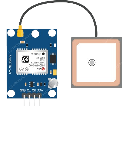
 Design with GPS NEO 6M in Cirkit Designer
Introduction
The GPS NEO 6M is a compact GPS receiver module that provides accurate positioning data using the Global Positioning System. It features high sensitivity, low power consumption, and reliable performance, making it ideal for a wide range of applications. This module is commonly used in robotics, drones, navigation systems, and other projects requiring precise location tracking. Its onboard antenna and UART interface make it easy to integrate into microcontroller-based systems.
Explore Projects Built with GPS NEO 6M
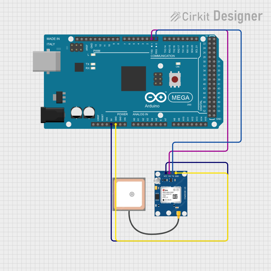 Open Project in Cirkit Designer
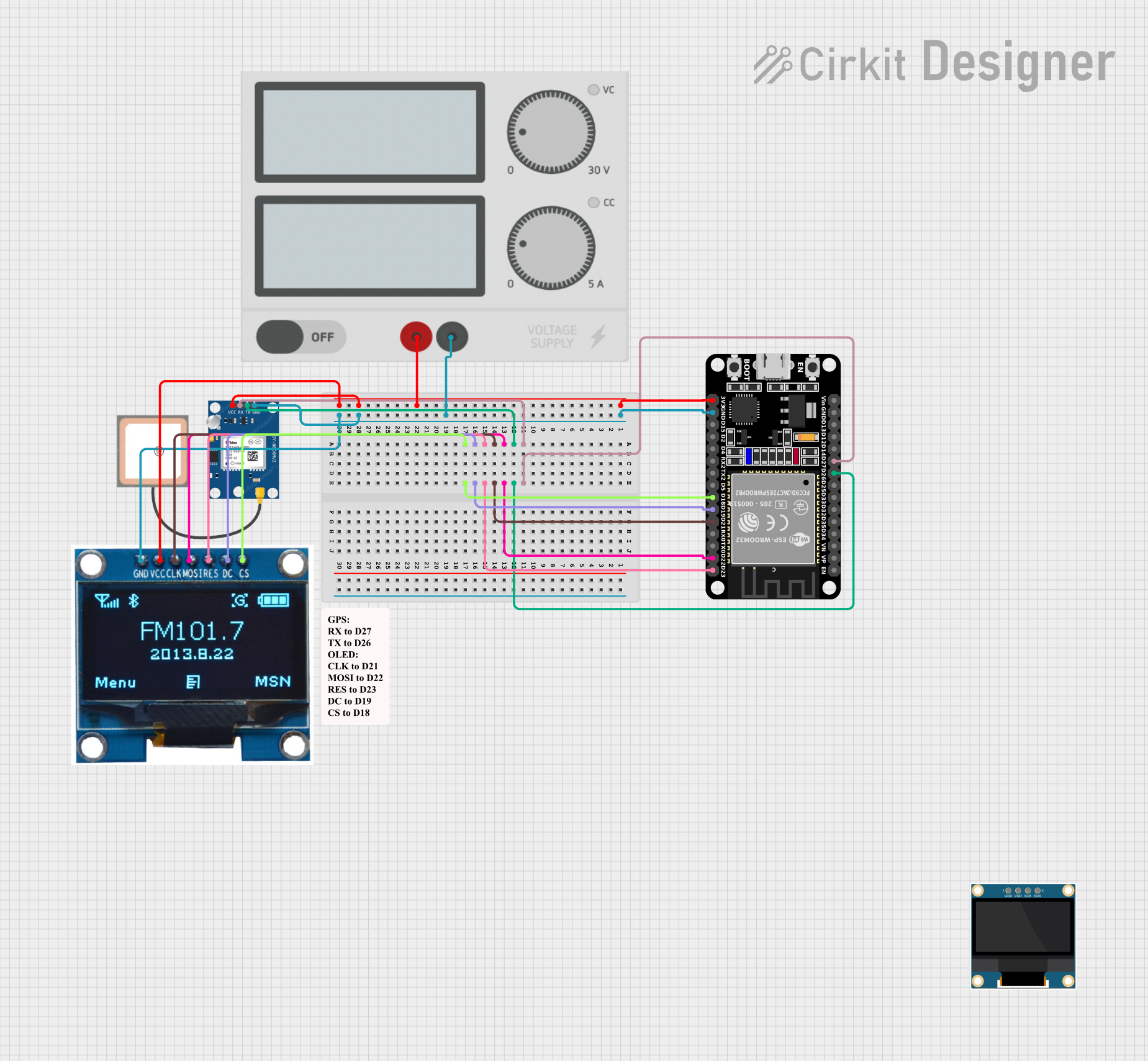 Open Project in Cirkit Designer
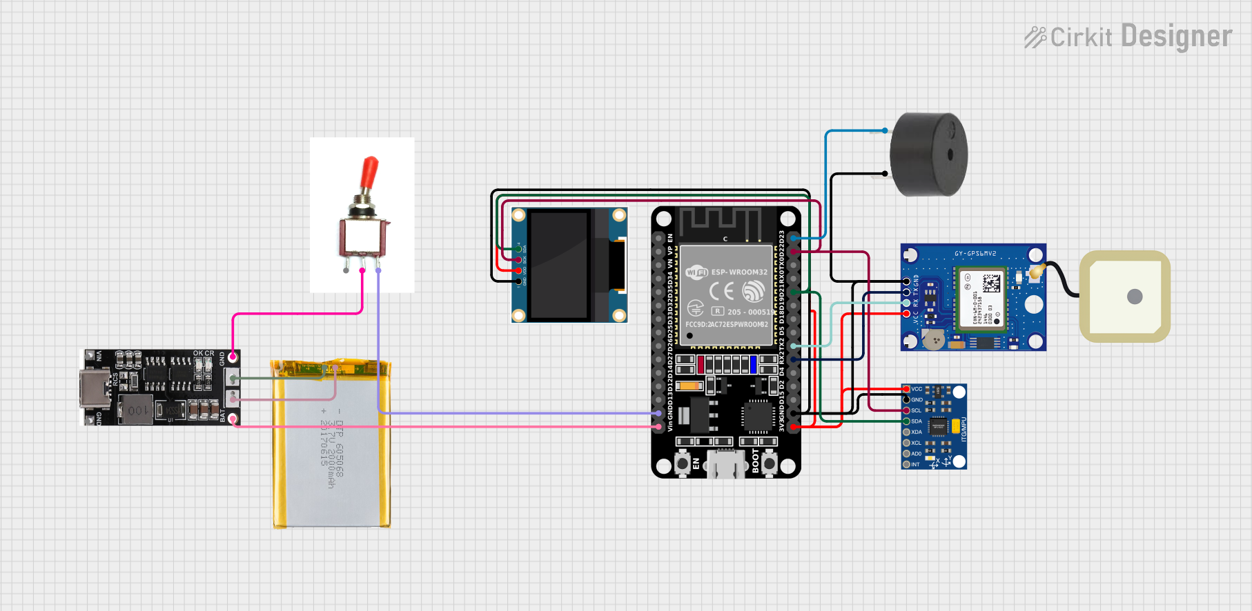 Open Project in Cirkit Designer
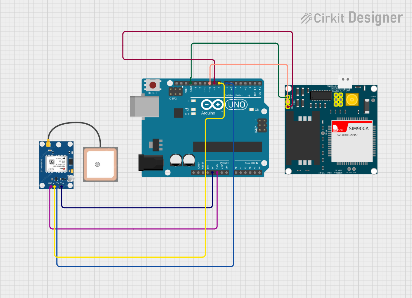 Open Project in Cirkit Designer
Explore Projects Built with GPS NEO 6M
Open Project in Cirkit DesignerOpen Project in Cirkit DesignerOpen Project in Cirkit DesignerOpen Project in Cirkit DesignerTechnical Specifications
- Model: NEO 6M
- Input Voltage: 3.3V to 5V
- Current Consumption: ~45mA
- Communication Protocol: UART (default baud rate: 9600 bps)
- Positioning Accuracy: 2.5 meters (CEP)
- Update Rate: 1 Hz (default), configurable up to 5 Hz
- Antenna: Ceramic patch antenna (onboard)
- Backup Power: Supports a rechargeable battery for maintaining data (RTC and ephemeris)
- Operating Temperature: -40°C to +85°C
- Dimensions: 25mm x 35mm x 6mm
Pin Configuration and Descriptions
| Pin | Name | Description |
|---|---|---|
| 1 | VCC | Power input (3.3V to 5V). Supplies power to the module. |
| 2 | GND | Ground. Connect to the ground of the power supply or circuit. |
| 3 | TXD | Transmit data pin. Sends GPS data to the microcontroller or other devices. |
| 4 | RXD | Receive data pin. Receives configuration commands from the microcontroller. |
Usage Instructions
How to Use the GPS NEO 6M in a Circuit
- Power the Module: Connect the VCC pin to a 3.3V or 5V power source and the GND pin to the ground.
- Connect to a Microcontroller:
- Connect the TXD pin of the GPS module to the RX pin of the microcontroller.
- Connect the RXD pin of the GPS module to the TX pin of the microcontroller.
- Antenna Placement: Ensure the onboard antenna has a clear view of the sky for optimal satellite reception.
- Read GPS Data: Use the UART interface to read NMEA sentences (e.g., GPGGA, GPRMC) from the module. These sentences contain information such as latitude, longitude, altitude, and time.
Important Considerations and Best Practices
- Power Supply: Use a stable power source to avoid data corruption or module resets.
- Antenna Orientation: Place the module in an open area with minimal obstructions for better satellite signal reception.
- Baud Rate Configuration: The default baud rate is 9600 bps. If needed, you can configure it using specific commands.
- Backup Battery: Connect a backup battery to the module to retain satellite data and reduce cold start time.
Example: Connecting GPS NEO 6M to Arduino UNO
Below is an example code to interface the GPS NEO 6M with an Arduino UNO and read GPS data.
#include <SoftwareSerial.h>

// Define RX and TX pins for SoftwareSerial
SoftwareSerial gpsSerial(4, 3); // RX = Pin 4, TX = Pin 3

void setup() {
  Serial.begin(9600);          // Initialize Serial Monitor at 9600 bps
  gpsSerial.begin(9600);       // Initialize GPS module at 9600 bps
  Serial.println("GPS NEO 6M Test");
}

void loop() {
  // Check if data is available from the GPS module
  while (gpsSerial.available()) {
    char c = gpsSerial.read(); // Read one character from GPS module
    Serial.print(c);           // Print the character to Serial Monitor
  }
}
Note:
- Connect the GPS module's TXD pin to Arduino's pin 4 and RXD pin to Arduino's pin 3.
- Open the Serial Monitor to view the raw NMEA sentences from the GPS module.
Troubleshooting and FAQs
Common Issues and Solutions
No GPS Data Received:
- Ensure the module is powered correctly (check VCC and GND connections).
- Verify the TXD and RXD connections between the GPS module and the microcontroller.
- Check the baud rate settings in your code (default is 9600 bps).
Poor Satellite Signal:
- Place the module in an open area with a clear view of the sky.
- Avoid placing the module near metal objects or inside enclosures that block signals.
Module Not Responding:
- Ensure the power supply voltage is within the specified range (3.3V to 5V).
- Check for loose or incorrect wiring.
Data Corruption:
- Use a stable power source to prevent voltage fluctuations.
- Ensure the UART connections are secure and free from noise.
FAQs
Q: Can the GPS NEO 6M work indoors?
A: The module may work indoors near windows, but signal reception is significantly reduced. For best results, use it outdoors.Q: How long does it take to get a GPS fix?
A: A cold start typically takes 30-60 seconds, while a warm start (with backup battery) takes 1-5 seconds.Q: Can I change the update rate of the module?
A: Yes, the update rate can be configured up to 5 Hz using specific configuration commands.Q: What is the default communication protocol?
A: The module uses UART with a default baud rate of 9600 bps.
By following this documentation, you can effectively integrate and troubleshoot the GPS NEO 6M module in your projects.