How to Use HC-SR501 Motion sensor: Examples, Pinouts, and Specs
Introduction
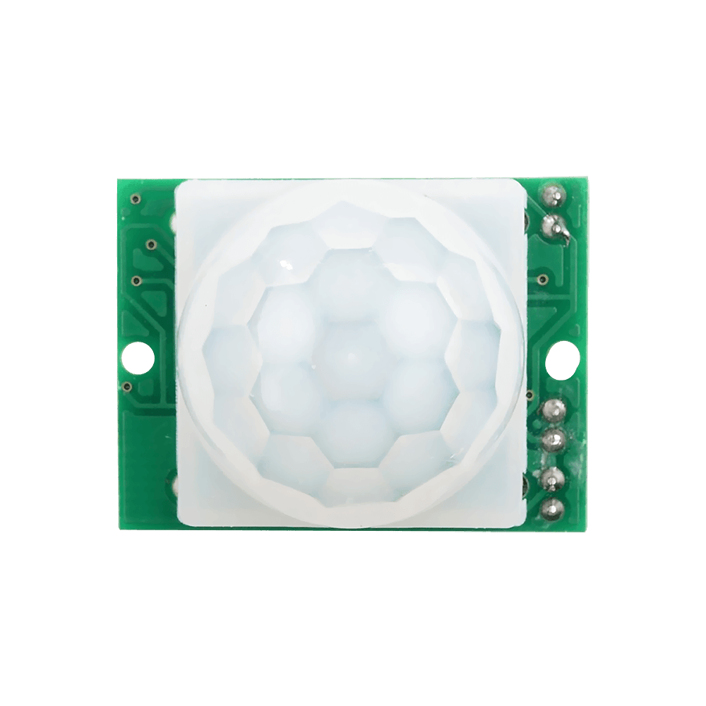
The HC-SR501 is a passive infrared (PIR) motion sensor designed to detect motion by sensing changes in infrared radiation emitted by objects in its field of view. This sensor is widely used in security systems, home automation, and robotics projects to trigger actions such as turning on lights, activating alarms, or starting recording devices when motion is detected.
Explore Projects Built with HC-SR501 Motion sensor
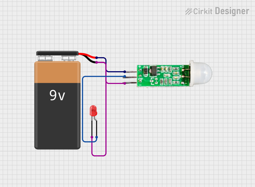
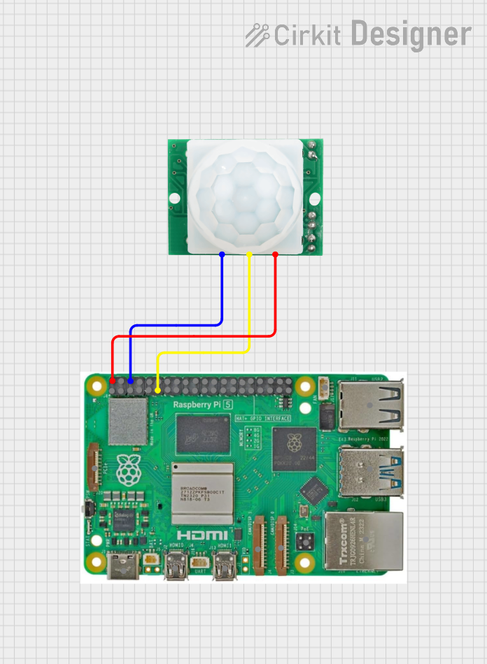
Explore Projects Built with HC-SR501 Motion sensor
Common Applications
- Security systems for detecting intruders
- Automatic lighting systems
- Smart home automation
- Robotics for motion detection
- Energy-saving devices
Technical Specifications
The HC-SR501 is a versatile and adjustable motion sensor with the following key specifications:
| Parameter | Value |
|---|---|
| Operating Voltage | 4.5V to 20V DC |
| Operating Current | < 60 µA |
| Detection Range | Up to 7 meters (adjustable) |
| Detection Angle | Approximately 120° |
| Trigger Modes | Repeatable (default) and Non-repeatable |
| Output Voltage (High) | 3.3V |
| Output Voltage (Low) | 0V |
| Delay Time | Adjustable (0.3 seconds to 5 minutes) |
| Sensitivity | Adjustable via onboard potentiometer |
| Dimensions | 32mm x 24mm x 25mm |
Pin Configuration
The HC-SR501 has three pins for interfacing with external circuits:
| Pin | Name | Description |
|---|---|---|
| 1 | VCC | Power supply input (4.5V to 20V DC) |
| 2 | OUT | Digital output pin (HIGH when motion is detected) |
| 3 | GND | Ground connection |
Usage Instructions
Connecting the HC-SR501 to a Circuit
- Power Supply: Connect the
VCCpin to a DC power source (4.5V to 20V) and theGNDpin to the ground. - Output Signal: Connect the
OUTpin to a microcontroller's digital input pin or directly to an external device (e.g., an LED or buzzer). - Adjustments:
- Use the sensitivity potentiometer to adjust the detection range.
- Use the delay potentiometer to set the duration for which the output remains HIGH after motion is detected.
Example: Using HC-SR501 with Arduino UNO
Below is an example of how to connect and use the HC-SR501 with an Arduino UNO to control an LED when motion is detected.
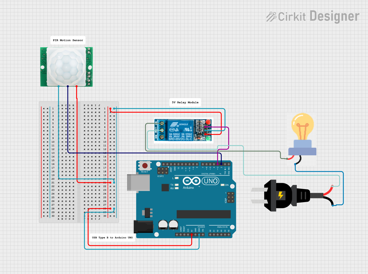
Circuit Diagram
- Connect the
VCCpin of the HC-SR501 to the Arduino's5Vpin. - Connect the
GNDpin of the HC-SR501 to the Arduino'sGNDpin. - Connect the
OUTpin of the HC-SR501 to Arduino digital pin2. - Connect an LED to Arduino digital pin
13with a 220-ohm resistor in series.
Arduino Code
// HC-SR501 Motion Sensor with Arduino UNO
// This code turns on an LED when motion is detected.

const int pirPin = 2;  // HC-SR501 OUT pin connected to digital pin 2
const int ledPin = 13; // LED connected to digital pin 13

void setup() {
  pinMode(pirPin, INPUT);  // Set PIR sensor pin as input
  pinMode(ledPin, OUTPUT); // Set LED pin as output
  Serial.begin(9600);      // Initialize serial communication for debugging
}

void loop() {
  int motionDetected = digitalRead(pirPin); // Read PIR sensor output

  if (motionDetected == HIGH) { // If motion is detected
    digitalWrite(ledPin, HIGH); // Turn on the LED
    Serial.println("Motion detected!"); // Print message to serial monitor
  } else {
    digitalWrite(ledPin, LOW);  // Turn off the LED
  }

  delay(100); // Small delay to stabilize readings
}
Important Considerations
- Warm-up Time: The HC-SR501 requires a warm-up period of approximately 30 seconds after power-up to stabilize.
- Trigger Modes:
- Repeatable Mode: The output remains HIGH as long as motion is detected. This is the default mode.
- Non-repeatable Mode: The output goes LOW after the delay time, even if motion is still detected.
- The trigger mode can be changed by adjusting the onboard jumper.
- Environmental Factors: Avoid placing the sensor near heat sources or in direct sunlight, as these can interfere with its operation.
Troubleshooting and FAQs
Common Issues
Sensor Not Detecting Motion:
- Ensure the sensor is powered correctly (4.5V to 20V DC).
- Check the sensitivity potentiometer and adjust it as needed.
- Verify that the sensor is not obstructed or placed in an unsuitable environment.
False Triggers:
- Avoid placing the sensor near heat sources, such as heaters or incandescent bulbs.
- Ensure the sensor is not exposed to direct sunlight or strong air currents.
Output Stuck HIGH or LOW:
- Check the trigger mode jumper and ensure it is set correctly.
- Verify the connections to the microcontroller or external circuit.
FAQs
Q: Can the HC-SR501 detect motion through glass?
A: No, the HC-SR501 cannot detect motion through glass, as infrared radiation does not pass through it effectively.
Q: How do I increase the detection range?
A: Adjust the sensitivity potentiometer clockwise to increase the detection range. Note that increasing sensitivity may also increase false triggers.
Q: What is the maximum detection angle of the HC-SR501?
A: The sensor has a detection angle of approximately 120°, which is determined by the Fresnel lens.
Q: Can I use the HC-SR501 with a 3.3V microcontroller?
A: Yes, the output of the HC-SR501 is 3.3V, making it compatible with 3.3V logic levels. However, the sensor itself requires a power supply of at least 4.5V.
By following this documentation, you can effectively integrate the HC-SR501 motion sensor into your projects for reliable motion detection.