How to Use 3.5mm Jack: Examples, Pinouts, and Specs
Introduction
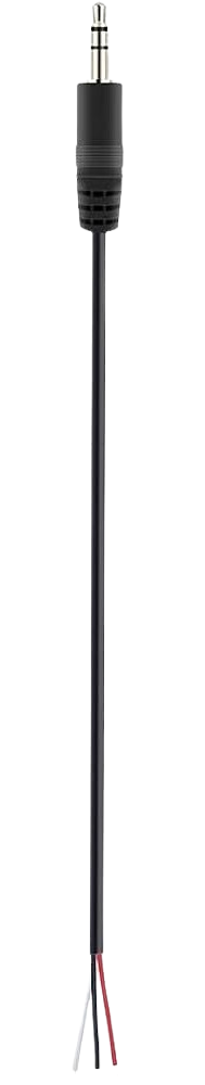
A 3.5mm jack is a ubiquitous audio connector used in a variety of audio devices, including headphones, microphones, and other audio equipment. It typically features three conductors: left audio, right audio, and ground. This connector is widely used due to its compact size and reliable performance in transmitting audio signals.
Explore Projects Built with 3.5mm Jack
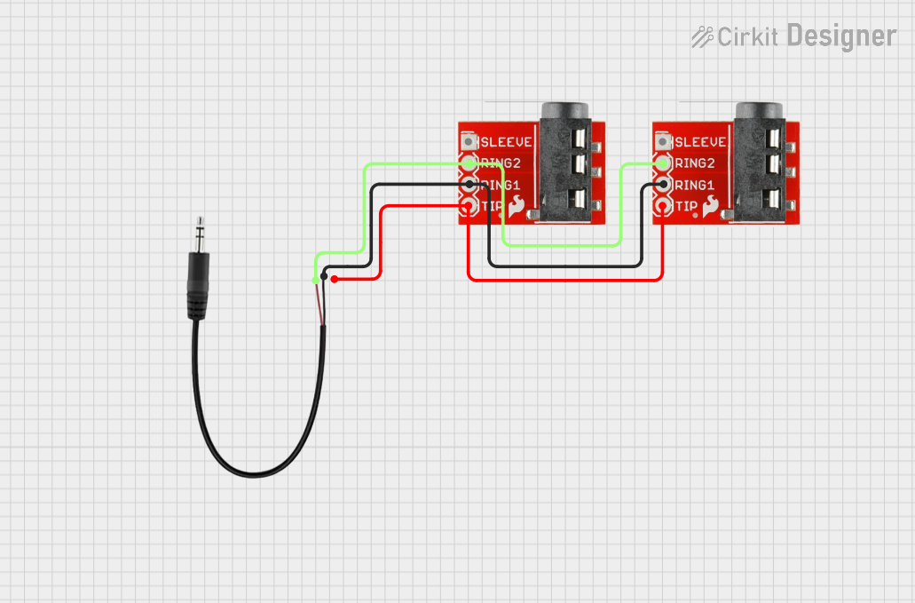

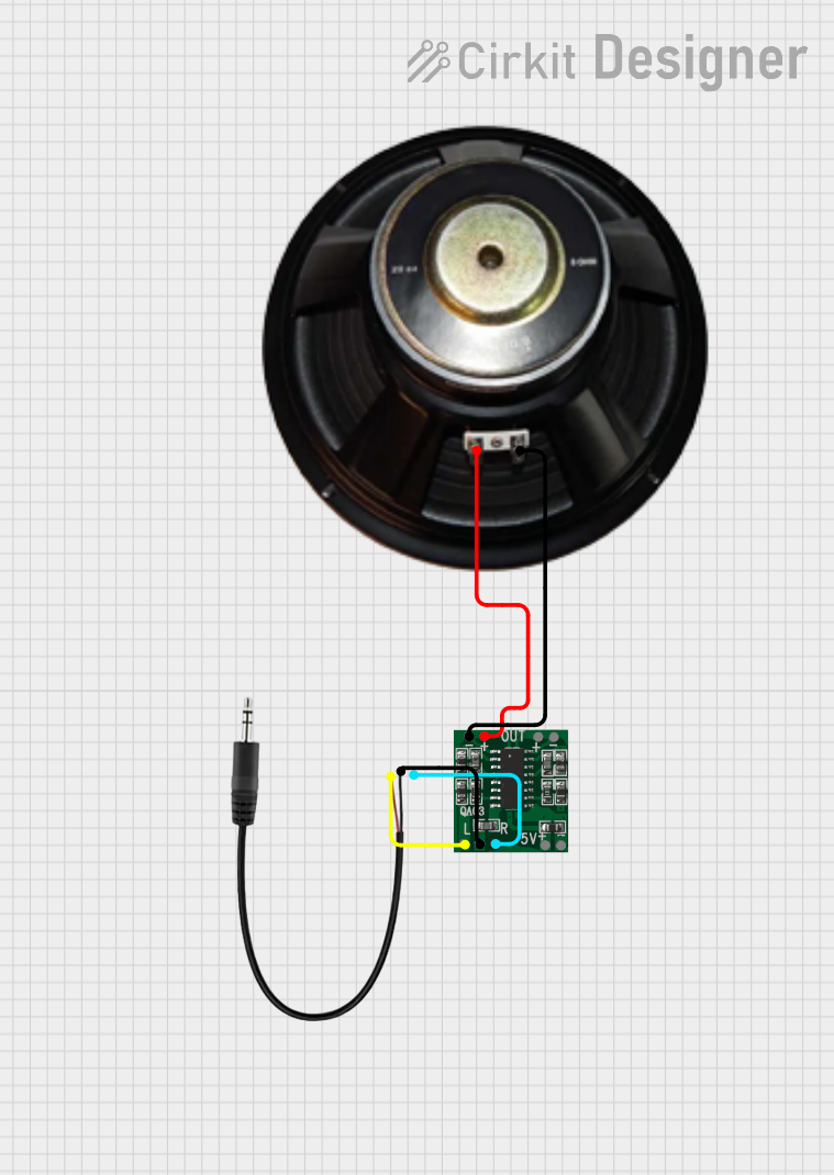
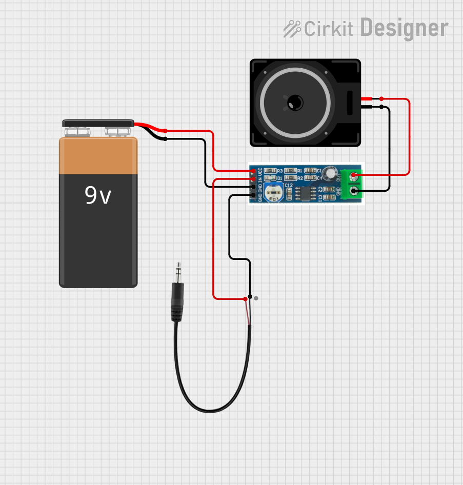
Explore Projects Built with 3.5mm Jack
Technical Specifications
Key Technical Details
| Parameter | Value |
|---|---|
| Connector Type | 3.5mm (1/8 inch) TRS |
| Conductors | 3 (Tip, Ring, Sleeve) |
| Voltage Rating | Typically 5V (depends on device) |
| Current Rating | Typically 500mA (depends on device) |
| Material | Metal (usually gold or nickel plated) |
| Insulation | Plastic or rubber |
Pin Configuration and Descriptions
| Pin | Name | Description |
|---|---|---|
| Tip | Left | Left audio channel |
| Ring | Right | Right audio channel |
| Sleeve | Ground | Common ground for both channels |
Usage Instructions
How to Use the Component in a Circuit
- Identify the Pins: The 3.5mm jack has three main parts: Tip, Ring, and Sleeve. The Tip is for the left audio channel, the Ring is for the right audio channel, and the Sleeve is the ground.
- Connect to Audio Source: Connect the Tip to the left audio output, the Ring to the right audio output, and the Sleeve to the ground of your audio source.
- Soldering: If you are using a 3.5mm jack with solder terminals, carefully solder the wires to the respective terminals. Ensure that there are no short circuits between the terminals.
- Mounting: Secure the 3.5mm jack in its designated place on your device or enclosure.
Important Considerations and Best Practices
- Avoid Short Circuits: Ensure that the connections are secure and there are no short circuits between the Tip, Ring, and Sleeve.
- Use Heat Shrink Tubing: To prevent accidental shorts and provide strain relief, use heat shrink tubing over the soldered connections.
- Check Polarity: Double-check the polarity of the connections to avoid damaging your audio equipment.
- Use Proper Tools: Use a good quality soldering iron and appropriate solder to ensure reliable connections.
Example: Connecting a 3.5mm Jack to an Arduino UNO
To read audio signals from a 3.5mm jack using an Arduino UNO, you can use the following example code. This example assumes you are using an analog input to read the audio signal.
Circuit Diagram
- Connect the Tip (Left audio) to Arduino analog pin A0.
- Connect the Ring (Right audio) to Arduino analog pin A1.
- Connect the Sleeve (Ground) to Arduino GND.
Arduino Code
// Define analog pins for left and right audio channels
const int leftAudioPin = A0;
const int rightAudioPin = A1;

void setup() {
  // Initialize serial communication for debugging
  Serial.begin(9600);
}

void loop() {
  // Read the analog values from the left and right audio channels
  int leftAudioValue = analogRead(leftAudioPin);
  int rightAudioValue = analogRead(rightAudioPin);

  // Print the audio values to the serial monitor
  Serial.print("Left Audio: ");
  Serial.print(leftAudioValue);
  Serial.print(" | Right Audio: ");
  Serial.println(rightAudioValue);

  // Add a small delay to avoid overwhelming the serial monitor
  delay(100);
}
Troubleshooting and FAQs
Common Issues Users Might Face
No Audio Signal Detected:
- Solution: Check the connections to ensure they are secure and correctly mapped to the Tip, Ring, and Sleeve.
Audio Distortion:
- Solution: Ensure that the audio source is not overdriving the input. Use appropriate resistors or voltage dividers if necessary.
Short Circuits:
- Solution: Inspect the solder joints and use heat shrink tubing to prevent accidental shorts.
FAQs
Q: Can I use a 3.5mm jack for mono audio? A: Yes, you can use a 3.5mm jack for mono audio by connecting either the Tip or Ring to the audio signal and the Sleeve to ground.
Q: What is the difference between TRS and TRRS connectors? A: TRS stands for Tip-Ring-Sleeve and has three conductors. TRRS stands for Tip-Ring-Ring-Sleeve and has four conductors, typically used for combined audio and microphone connections.
Q: Can I use a 3.5mm jack for digital signals? A: While primarily designed for analog audio, a 3.5mm jack can be used for low-frequency digital signals, but it is not recommended for high-speed digital communication.
This documentation provides a comprehensive guide to understanding, using, and troubleshooting a 3.5mm jack in various applications. Whether you are a beginner or an experienced user, this guide aims to help you make the most of this versatile audio connector.