How to Use USB-C - 4 Pin Cable: Examples, Pinouts, and Specs
Introduction
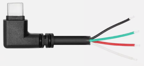
The USB-C - 4 Pin Cable is a versatile and widely used component designed for data transfer and charging between devices equipped with USB-C ports. This cable is known for its reversible connector, which simplifies the connection process by allowing the plug to be inserted either way. It is commonly used in smartphones, tablets, laptops, and various other electronic devices.
Explore Projects Built with USB-C - 4 Pin Cable


Explore Projects Built with USB-C - 4 Pin Cable
Common Applications and Use Cases
- Data Transfer: Facilitates high-speed data transfer between devices.
- Charging: Provides power to charge devices such as smartphones, tablets, and laptops.
- Peripheral Connectivity: Connects peripherals like external hard drives, keyboards, and mice to computers.
- Audio and Video Transmission: Supports audio and video output to compatible devices.
Technical Specifications
Key Technical Details
| Specification | Value |
|---|---|
| Connector Type | USB-C |
| Number of Pins | 4 |
| Voltage Rating | 5V |
| Current Rating | Up to 3A |
| Data Transfer Rate | Up to 480 Mbps (USB 2.0) |
| Cable Length | Varies (typically 1m to 2m) |
Pin Configuration and Descriptions
| Pin Number | Name | Description |
|---|---|---|
| 1 | VBUS | Power supply (5V) |
| 2 | D- | Data transfer (negative) |
| 3 | D+ | Data transfer (positive) |
| 4 | GND | Ground |
Usage Instructions
How to Use the Component in a Circuit
- Identify the Pins: Ensure you correctly identify the VBUS, D-, D+, and GND pins on the USB-C connector.
- Connect to Power Source: Connect the VBUS pin to a 5V power source and the GND pin to the ground.
- Data Transfer: Connect the D- and D+ pins to the corresponding data lines of the device you wish to communicate with.
- Secure Connections: Ensure all connections are secure to prevent data loss or power issues.
Important Considerations and Best Practices
- Cable Quality: Use high-quality cables to ensure reliable data transfer and charging.
- Avoid Overloading: Do not exceed the current rating of 3A to prevent overheating and potential damage.
- Proper Handling: Handle the cable with care to avoid physical damage to the connectors and wires.
- Compatibility: Ensure the devices you are connecting are compatible with USB-C standards.
Troubleshooting and FAQs
Common Issues Users Might Face
No Data Transfer:
- Solution: Check the connections of the D- and D+ pins. Ensure they are securely connected to the corresponding data lines.
Device Not Charging:
- Solution: Verify that the VBUS and GND pins are correctly connected to the power source and ground, respectively. Ensure the power source is functioning properly.
Slow Data Transfer:
- Solution: Ensure the cable is not damaged and is of high quality. Check for any interference or obstructions that might affect data transfer rates.
Solutions and Tips for Troubleshooting
- Check Connections: Always double-check all connections to ensure they are secure and correctly aligned.
- Test with Different Devices: If an issue persists, try using the cable with different devices to determine if the problem is with the cable or the device.
- Inspect for Damage: Regularly inspect the cable for any signs of wear or damage, such as frayed wires or bent connectors.
Example Code for Arduino UNO
If you are using the USB-C - 4 Pin Cable to connect an Arduino UNO to a computer for data transfer, you can use the following example code to establish serial communication:
// Example code to establish serial communication between Arduino UNO
// and a computer using a USB-C - 4 Pin Cable

void setup() {
  // Initialize serial communication at 9600 baud rate
  Serial.begin(9600);
}

void loop() {
  // Check if data is available to read
  if (Serial.available() > 0) {
    // Read the incoming byte
    char incomingByte = Serial.read();

    // Print the received byte to the Serial Monitor
    Serial.print("Received: ");
    Serial.println(incomingByte);
  }

  // Send a message to the Serial Monitor every second
  Serial.println("Hello from Arduino!");
  delay(1000);
}
This code initializes serial communication at a baud rate of 9600 and continuously checks for incoming data. When data is received, it prints the received byte to the Serial Monitor. Additionally, it sends a message to the Serial Monitor every second.
By following this documentation, users can effectively utilize the USB-C - 4 Pin Cable for various applications, ensuring reliable data transfer and charging.