How to Use 74HCT245: Examples, Pinouts, and Specs
Introduction
The 74HCT245 is an octal buffer/driver with 3-state outputs, manufactured by Texas Instruments (TI). This component is designed for high-speed data transmission and is widely used in digital circuits to interface between different voltage levels. It provides signal buffering and isolation, ensuring reliable communication between devices operating at different logic levels.
Explore Projects Built with 74HCT245


Explore Projects Built with 74HCT245
Common Applications and Use Cases
- Interfacing between microcontrollers and peripheral devices
- Signal buffering in digital systems
- Voltage level translation in mixed-voltage environments
- Driving long data buses or multiple loads
- Memory address/data multiplexing
Technical Specifications
The 74HCT245 is part of the HCT logic family, which is compatible with TTL (Transistor-Transistor Logic) voltage levels. Below are the key technical details and pin configuration:
Key Technical Details
| Parameter | Value |
|---|---|
| Supply Voltage (Vcc) | 4.5V to 5.5V |
| Input Voltage (VI) | 0V to 5.5V |
| Output Voltage (VO) | 0V to Vcc |
| High-Level Input Voltage | 2.0V (minimum) |
| Low-Level Input Voltage | 0.8V (maximum) |
| Output Current (IO) | ±6 mA per output |
| Propagation Delay (tpd) | 10 ns (typical at Vcc = 5V) |
| Operating Temperature | -40°C to +125°C |
| Package Types | SOIC, PDIP, TSSOP, and others |
Pin Configuration and Descriptions
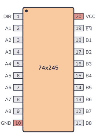
The 74HCT245 has 20 pins, as shown in the table below:
| Pin Number | Pin Name | Description |
|---|---|---|
| 1 | DIR | Direction control (data flow direction) |
| 2-9 | A1-A8 | Data inputs/outputs (Bus A) |
| 10 | GND | Ground |
| 11-18 | B1-B8 | Data inputs/outputs (Bus B) |
| 19 | OE̅ | Output Enable (active low) |
| 20 | Vcc | Positive supply voltage |
Functional Description
- DIR (Direction Control): Determines the direction of data flow:
- High (1): Data flows from Bus A to Bus B.
- Low (0): Data flows from Bus B to Bus A.
- OE̅ (Output Enable): Enables or disables the outputs:
- Low (0): Outputs are enabled.
- High (1): Outputs are in high-impedance (3-state) mode.
Usage Instructions
The 74HCT245 is straightforward to use in digital circuits. Below are the steps and considerations for proper usage:
How to Use the Component in a Circuit
Power Supply:
- Connect the Vcc pin to a 5V power supply.
- Connect the GND pin to the ground of the circuit.
Direction Control (DIR):
- Set the DIR pin high or low depending on the desired data flow direction.
Output Enable (OE̅):
- Pull the OE̅ pin low to enable the outputs.
- Pull the OE̅ pin high to disable the outputs (3-state mode).
Data Connections:
- Connect the A1-A8 pins to one data bus and the B1-B8 pins to another.
- Ensure that the data buses are compatible with the voltage levels of the 74HCT245.
Important Considerations and Best Practices
- Voltage Compatibility: Ensure that the input and output voltage levels are within the specified range.
- Decoupling Capacitor: Place a 0.1 µF ceramic capacitor close to the Vcc pin to filter noise and stabilize the power supply.
- Unused Inputs: Tie unused inputs to Vcc or GND to prevent floating inputs, which can cause erratic behavior.
- 3-State Outputs: When the outputs are in high-impedance mode, ensure that external pull-up or pull-down resistors are used if necessary.
Example: Interfacing with an Arduino UNO
The 74HCT245 can be used to interface an Arduino UNO with a 5V data bus. Below is an example Arduino sketch to control the direction and enable pins:
// Define pin connections for the 74HCT245
const int dirPin = 2;  // Direction control pin (DIR)
const int oePin = 3;   // Output Enable pin (OE̅)

void setup() {
  // Set DIR and OE̅ pins as outputs
  pinMode(dirPin, OUTPUT);
  pinMode(oePin, OUTPUT);

  // Initialize the 74HCT245
  digitalWrite(dirPin, HIGH);  // Set data flow from A to B
  digitalWrite(oePin, LOW);    // Enable outputs
}

void loop() {
  // Example: Toggle direction every 2 seconds
  digitalWrite(dirPin, HIGH);  // Data flows from A to B
  delay(2000);                 // Wait for 2 seconds
  digitalWrite(dirPin, LOW);   // Data flows from B to A
  delay(2000);                 // Wait for 2 seconds
}
Troubleshooting and FAQs
Common Issues and Solutions
Outputs Not Responding:
- Cause: OE̅ pin is not pulled low.
- Solution: Ensure that the OE̅ pin is connected to GND to enable the outputs.
Incorrect Data Flow:
- Cause: DIR pin is set incorrectly.
- Solution: Verify the logic level of the DIR pin and adjust it to match the desired data flow direction.
Floating Inputs:
- Cause: Unused inputs are left unconnected.
- Solution: Tie unused inputs to Vcc or GND to prevent erratic behavior.
Noise or Instability:
- Cause: Lack of proper decoupling.
- Solution: Add a 0.1 µF ceramic capacitor close to the Vcc pin.
FAQs
Q1: Can the 74HCT245 be used with 3.3V logic devices?
A1: Yes, the 74HCT245 is TTL-compatible and can interface with 3.3V logic devices as long as the input voltage levels meet the specified thresholds.
Q2: What happens if both DIR and OE̅ are set high?
A2: If OE̅ is high, the outputs will be in high-impedance mode regardless of the DIR pin state.
Q3: Can the 74HCT245 drive LEDs directly?
A3: No, the output current is limited to ±6 mA per pin. Use a transistor or driver circuit to drive LEDs.
Q4: Is the 74HCT245 suitable for bidirectional communication?
A4: Yes, the DIR pin allows for bidirectional data flow control, making it ideal for such applications.