How to Use Relay Board: Examples, Pinouts, and Specs
Introduction
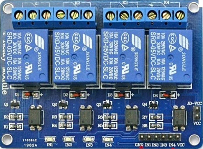
The Relay Board (Core Electronics CE05279) is a versatile circuit board equipped with multiple relays, which are electrically operated switches. This component enables the control of high-voltage or high-current devices using low-voltage signals, making it an essential tool for automation, home appliances, and industrial control systems.
Relay boards are widely used in applications such as home automation, motor control, lighting systems, and IoT projects. They provide a safe and efficient way to interface low-power microcontrollers, such as Arduino or Raspberry Pi, with high-power devices.
Explore Projects Built with Relay Board


Explore Projects Built with Relay Board
Technical Specifications
Below are the key technical details for the Core Electronics CE05279 Relay Board:
General Specifications
- Manufacturer: Core Electronics
- Part ID: CE05279
- Number of Relays: 4
- Relay Type: SPDT (Single Pole Double Throw)
- Control Voltage: 5V DC
- Trigger Current: 15-20mA per channel
- Maximum Load (per relay):
- AC: 250V at 10A
- DC: 30V at 10A
- Isolation: Optocoupler isolation for safe operation
- Dimensions: 75mm x 55mm x 20mm
Pin Configuration and Descriptions
The relay board has a set of input pins for control signals and output terminals for connecting external devices. Below is the pin configuration:
Input Pins
| Pin Name | Description |
|---|---|
| VCC | 5V DC power supply input |
| GND | Ground connection |
| IN1 | Control signal for Relay 1 (Active LOW) |
| IN2 | Control signal for Relay 2 (Active LOW) |
| IN3 | Control signal for Relay 3 (Active LOW) |
| IN4 | Control signal for Relay 4 (Active LOW) |
Output Terminals (Per Relay)
| Terminal | Description |
|---|---|
| COM | Common terminal for the relay |
| NO | Normally Open terminal (connected when relay is active) |
| NC | Normally Closed terminal (connected when relay is inactive) |
Usage Instructions
How to Use the Relay Board in a Circuit
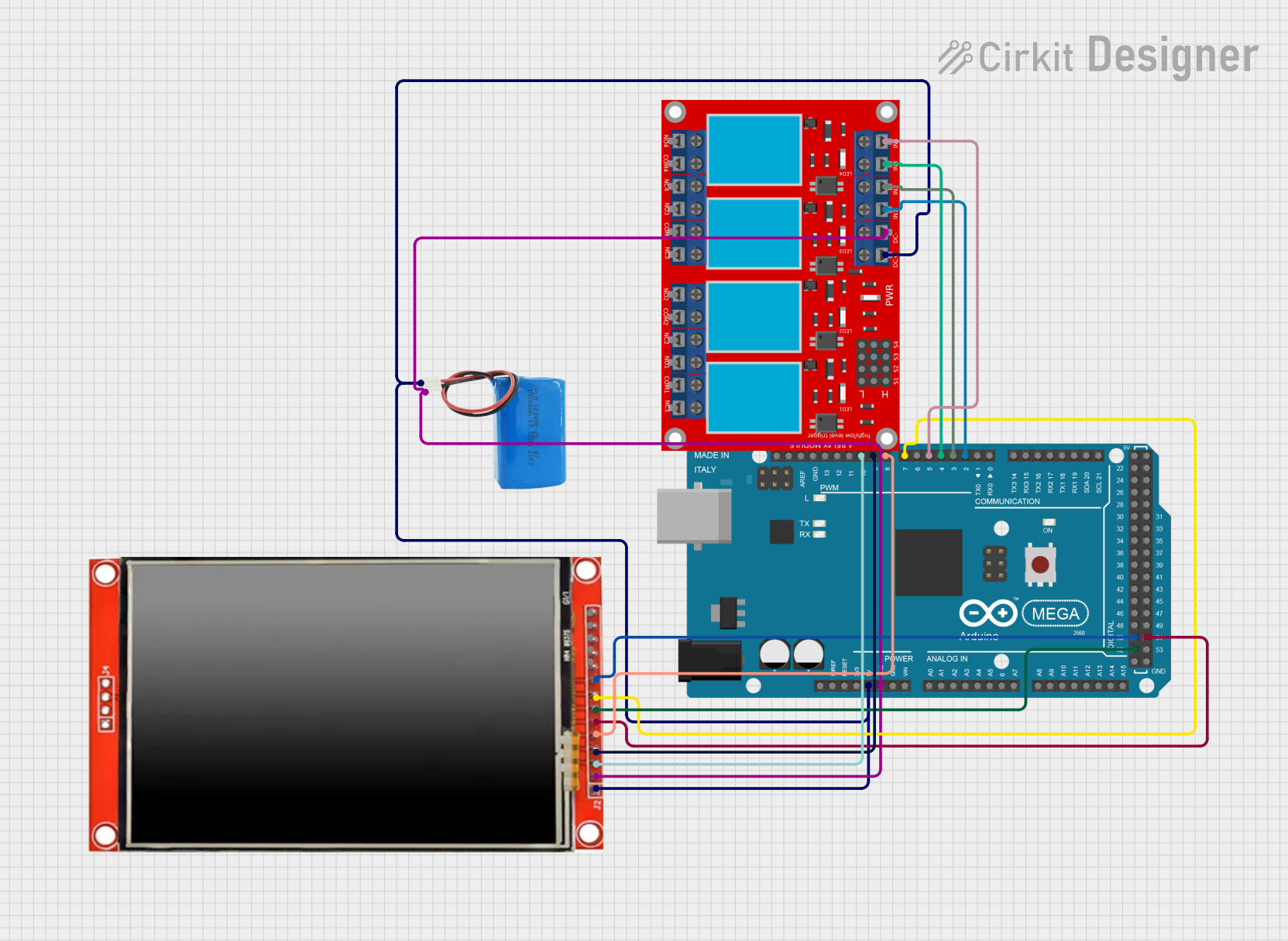
- Power the Relay Board: Connect the VCC pin to a 5V DC power source and the GND pin to the ground of your circuit.
- Connect Control Signals: Use digital output pins from a microcontroller (e.g., Arduino) to connect to the IN1, IN2, IN3, and IN4 pins. These pins are active LOW, meaning the relay will activate when the input signal is pulled LOW.
- Connect External Devices:
- For each relay, connect the device you want to control to the COM and NO/NC terminals.
- Use the NO terminal if you want the device to be off by default and turn on when the relay is activated.
- Use the NC terminal if you want the device to be on by default and turn off when the relay is activated.
- Write Control Code: Program your microcontroller to send LOW signals to the appropriate input pins to activate the relays.
Important Considerations and Best Practices
- Isolation: Ensure proper electrical isolation between the low-voltage control circuit and the high-voltage load to prevent damage or hazards.
- Power Supply: Use a stable 5V DC power source to avoid erratic relay behavior.
- Load Ratings: Do not exceed the maximum load ratings of the relays (250V AC at 10A or 30V DC at 10A).
- Active LOW Logic: Remember that the relays are triggered by a LOW signal. Plan your control logic accordingly.
Example Code for Arduino UNO
Below is an example code snippet to control the relay board using an Arduino UNO:
// Example code to control a 4-channel relay board (CE05279) with Arduino UNO

// Define the relay control pins
#define RELAY1 2  // Relay 1 connected to digital pin 2
#define RELAY2 3  // Relay 2 connected to digital pin 3
#define RELAY3 4  // Relay 3 connected to digital pin 4
#define RELAY4 5  // Relay 4 connected to digital pin 5

void setup() {
  // Set relay pins as outputs
  pinMode(RELAY1, OUTPUT);
  pinMode(RELAY2, OUTPUT);
  pinMode(RELAY3, OUTPUT);
  pinMode(RELAY4, OUTPUT);

  // Initialize all relays to OFF (HIGH state)
  digitalWrite(RELAY1, HIGH);
  digitalWrite(RELAY2, HIGH);
  digitalWrite(RELAY3, HIGH);
  digitalWrite(RELAY4, HIGH);
}

void loop() {
  // Example: Turn on Relay 1 for 2 seconds, then turn it off
  digitalWrite(RELAY1, LOW);  // Activate Relay 1
  delay(2000);                // Wait for 2 seconds
  digitalWrite(RELAY1, HIGH); // Deactivate Relay 1
  delay(2000);                // Wait for 2 seconds

  // Repeat similar logic for other relays as needed
}
Troubleshooting and FAQs
Common Issues and Solutions
Relays Not Activating:
- Cause: Insufficient power supply or incorrect wiring.
- Solution: Ensure the VCC pin is connected to a stable 5V DC source and the GND pin is properly grounded.
Erratic Relay Behavior:
- Cause: Electrical noise or unstable power supply.
- Solution: Use decoupling capacitors near the power supply pins and ensure a clean power source.
Microcontroller Resetting When Relays Activate:
- Cause: High inrush current or insufficient power supply to the microcontroller.
- Solution: Use a separate power supply for the relay board and the microcontroller, or add a flyback diode across the relay coil.
Relay Stuck in ON/OFF State:
- Cause: Exceeding the relay's load ratings or damaged relay contacts.
- Solution: Verify the load ratings and replace the relay if necessary.
FAQs
Q: Can I use the relay board with a 3.3V microcontroller?
- A: Yes, but you may need a level shifter or transistor circuit to ensure proper triggering of the relays.
Q: Is the relay board suitable for controlling DC motors?
- A: Yes, as long as the motor's voltage and current ratings are within the relay's specifications.
Q: Can I control all four relays simultaneously?
- A: Yes, as long as your power supply can handle the combined current draw of all relays.
This documentation provides a comprehensive guide to using the Core Electronics CE05279 Relay Board effectively and safely.