Cirkit Designer
Your all-in-one circuit design IDE
Home /
Component Documentation
How to Use Flamer Sensor: Examples, Pinouts, and Specs
Introduction
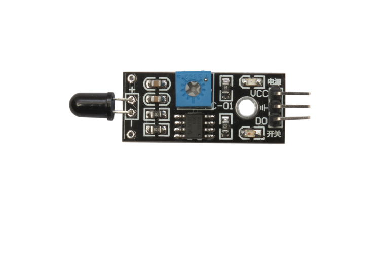
The Flame Sensor is an electronic component designed to detect the presence of flames or high temperatures. It is commonly used in fire detection and safety systems to provide early warnings of potential fire hazards. The sensor is sensitive to infrared light emitted by flames, making it an essential component in various safety and automation applications.
Explore Projects Built with Flamer Sensor
Flame Detection and Automatic Water Pump Activation System
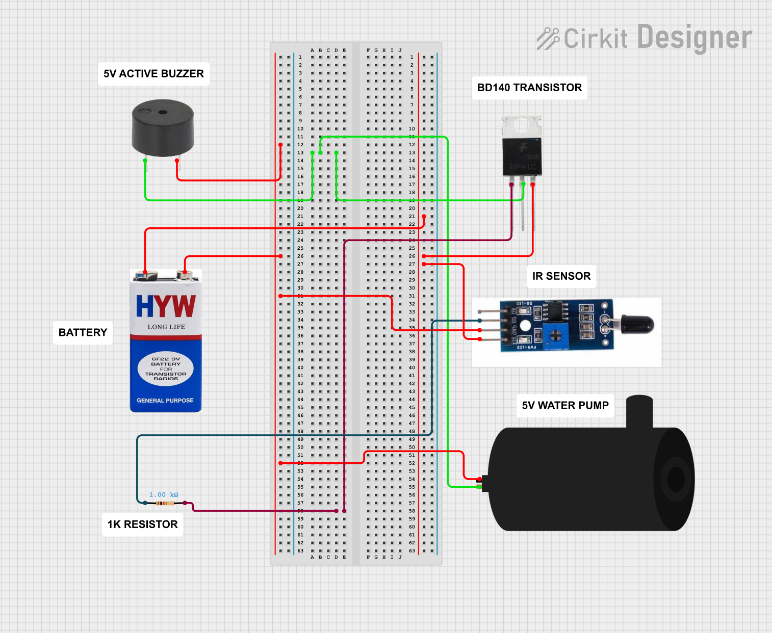
This circuit features a heat flame sensor that likely triggers a response when detecting heat or flame. The sensor's digital output (DO) is connected through a resistor to a TIP41C transistor, which acts as a switch for a buzzer and a water pump, indicating that the circuit is designed to sound an alarm and possibly activate a water pump in the event of detecting a flame. The 9V battery powers the circuit, and all components share a common ground.
Arduino Flame Detection System with Active-Low Sensor
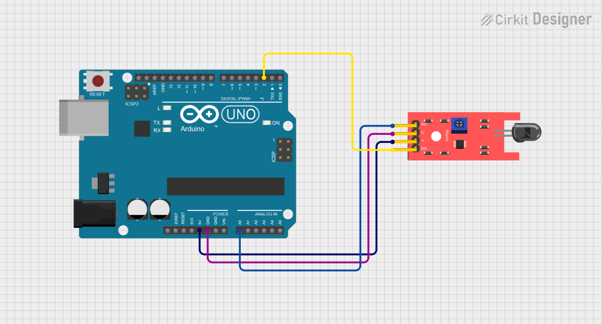
This circuit utilizes an Arduino UNO and a flame sensor to detect the presence of flames. The sensor's digital output is connected to the Arduino, which processes the signal and activates an onboard LED to indicate flame detection, while also providing optional analog logging of sensor data.
Arduino UNO Based Multi-Flame Sensor Detection System
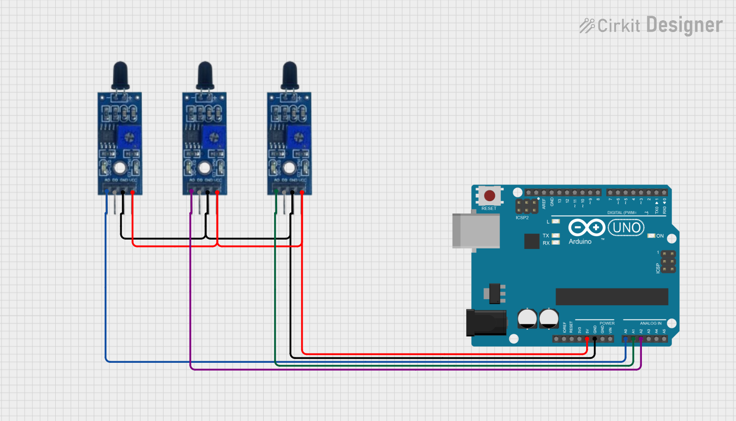
This circuit is designed to monitor for the presence of flames using three flame sensors connected to an Arduino UNO. Each flame sensor's analog output is connected to a separate analog input on the Arduino, allowing the microcontroller to read the intensity of the flame detected by each sensor. The 5V and GND pins of the Arduino provide power to the flame sensors.
Arduino UNO Based Multi-Sensor Safety System with Servo Control and LCD Feedback
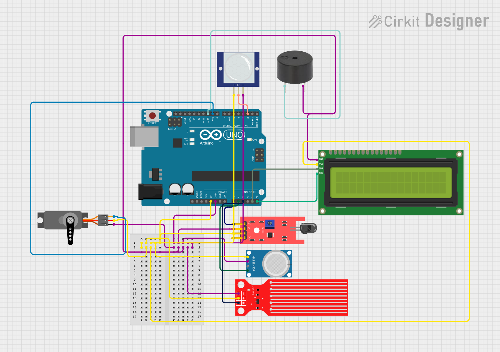
This circuit is a multi-sensor monitoring system controlled by an Arduino UNO microcontroller. It includes a flame sensor, gas sensor (MQ-4), water level sensor, PIR motion sensor, a servo motor, a buzzer, and an I2C LCD display for alerts. The system is designed to detect fire, gas leaks, intruders, and water levels, providing visual alerts on the LCD and audible alerts through the buzzer, with the servo motor potentially used for automated responses such as closing a valve or door.
Explore Projects Built with Flamer Sensor
Flame Detection and Automatic Water Pump Activation System
This circuit features a heat flame sensor that likely triggers a response when detecting heat or flame. The sensor's digital output (DO) is connected through a resistor to a TIP41C transistor, which acts as a switch for a buzzer and a water pump, indicating that the circuit is designed to sound an alarm and possibly activate a water pump in the event of detecting a flame. The 9V battery powers the circuit, and all components share a common ground.
Arduino Flame Detection System with Active-Low Sensor
This circuit utilizes an Arduino UNO and a flame sensor to detect the presence of flames. The sensor's digital output is connected to the Arduino, which processes the signal and activates an onboard LED to indicate flame detection, while also providing optional analog logging of sensor data.
Arduino UNO Based Multi-Flame Sensor Detection System
This circuit is designed to monitor for the presence of flames using three flame sensors connected to an Arduino UNO. Each flame sensor's analog output is connected to a separate analog input on the Arduino, allowing the microcontroller to read the intensity of the flame detected by each sensor. The 5V and GND pins of the Arduino provide power to the flame sensors.
Arduino UNO Based Multi-Sensor Safety System with Servo Control and LCD Feedback
This circuit is a multi-sensor monitoring system controlled by an Arduino UNO microcontroller. It includes a flame sensor, gas sensor (MQ-4), water level sensor, PIR motion sensor, a servo motor, a buzzer, and an I2C LCD display for alerts. The system is designed to detect fire, gas leaks, intruders, and water levels, providing visual alerts on the LCD and audible alerts through the buzzer, with the servo motor potentially used for automated responses such as closing a valve or door.
Common Applications and Use Cases
- Fire detection systems
- Safety and security systems
- Industrial automation
- Home automation
- Robotics
Technical Specifications
Key Technical Details
| Parameter | Value |
|---|---|
| Operating Voltage | 3.3V to 5V |
| Current Consumption | 20mA (typical) |
| Detection Range | Up to 100 cm (depending on flame size) |
| Spectral Range | 760 nm to 1100 nm |
| Output Type | Digital and Analog |
| Response Time | < 15 ms |
| Operating Temperature | -25°C to 85°C |
Pin Configuration and Descriptions
| Pin Number | Pin Name | Description |
|---|---|---|
| 1 | VCC | Power supply (3.3V to 5V) |
| 2 | GND | Ground |
| 3 | A0 | Analog output (proportional to flame intensity) |
| 4 | D0 | Digital output (HIGH when flame is detected) |
Usage Instructions
How to Use the Component in a Circuit
- Power Supply: Connect the VCC pin to a 3.3V or 5V power supply and the GND pin to the ground of your circuit.
- Analog Output: Connect the A0 pin to an analog input pin on your microcontroller to read the flame intensity.
- Digital Output: Connect the D0 pin to a digital input pin on your microcontroller to detect the presence of a flame.
Important Considerations and Best Practices
- Placement: Ensure the sensor is placed in a location where it has a clear line of sight to the area being monitored for flames.
- Sensitivity Adjustment: Some flame sensors come with a potentiometer to adjust the sensitivity. Adjust it according to your specific application needs.
- Interference: Avoid placing the sensor near sources of infrared light other than flames, as this may cause false positives.
- Testing: Regularly test the sensor to ensure it is functioning correctly and providing accurate readings.
Example Code for Arduino UNO
// Flame Sensor Example Code for Arduino UNO

const int flameSensorAnalogPin = A0; // Analog pin connected to A0
const int flameSensorDigitalPin = 2; // Digital pin connected to D0
const int ledPin = 13;               // LED pin for indication

void setup() {
  pinMode(flameSensorDigitalPin, INPUT); // Set digital pin as input
  pinMode(ledPin, OUTPUT);               // Set LED pin as output
  Serial.begin(9600);                    // Initialize serial communication
}

void loop() {
  int flameAnalogValue = analogRead(flameSensorAnalogPin); // Read analog value
  int flameDigitalValue = digitalRead(flameSensorDigitalPin); // Read digital value

  Serial.print("Analog Value: ");
  Serial.println(flameAnalogValue); // Print analog value to serial monitor

  if (flameDigitalValue == HIGH) {
    digitalWrite(ledPin, HIGH); // Turn on LED if flame is detected
    Serial.println("Flame detected!");
  } else {
    digitalWrite(ledPin, LOW); // Turn off LED if no flame is detected
    Serial.println("No flame detected.");
  }

  delay(500); // Wait for 500 milliseconds before next reading
}
Troubleshooting and FAQs
Common Issues Users Might Face
False Positives: The sensor may detect flames when there are none.
- Solution: Ensure there are no other sources of infrared light in the sensor's field of view. Adjust the sensitivity using the potentiometer if available.
No Detection: The sensor does not detect flames even when they are present.
- Solution: Check the power connections and ensure the sensor is properly aligned with the flame source. Verify that the sensor is within the specified detection range.
Inconsistent Readings: The sensor provides fluctuating or inconsistent readings.
- Solution: Stabilize the sensor's environment by reducing vibrations and electrical noise. Use proper shielding and grounding techniques.
Solutions and Tips for Troubleshooting
- Check Connections: Ensure all connections are secure and correctly wired.
- Power Supply: Verify that the power supply voltage is within the specified range.
- Sensor Alignment: Make sure the sensor is properly aligned with the area being monitored.
- Sensitivity Adjustment: Use the potentiometer to fine-tune the sensor's sensitivity.
- Regular Testing: Periodically test the sensor to ensure it is functioning correctly.
By following this documentation, users can effectively integrate the Flame Sensor into their projects, ensuring reliable flame detection and enhancing safety measures.