Cirkit Designer
Your all-in-one circuit design IDE
Home /
Component Documentation
How to Use ESP32-CAM MB FLIP: Examples, Pinouts, and Specs
Introduction
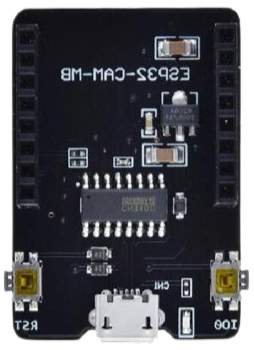
The ESP32-CAM MB FLIP is a compact and powerful Wi-Fi and Bluetooth-enabled development board designed for IoT applications, image processing, and wireless communication. It integrates an ESP32-S module with a built-in OV2640 camera, making it ideal for projects requiring video streaming, image capture, or remote monitoring. The "MB FLIP" variant includes a USB-to-serial adapter for easy programming and debugging, eliminating the need for an external FTDI module.
Explore Projects Built with ESP32-CAM MB FLIP
ESP32-CAM Controlled Wi-Fi Smart Lock
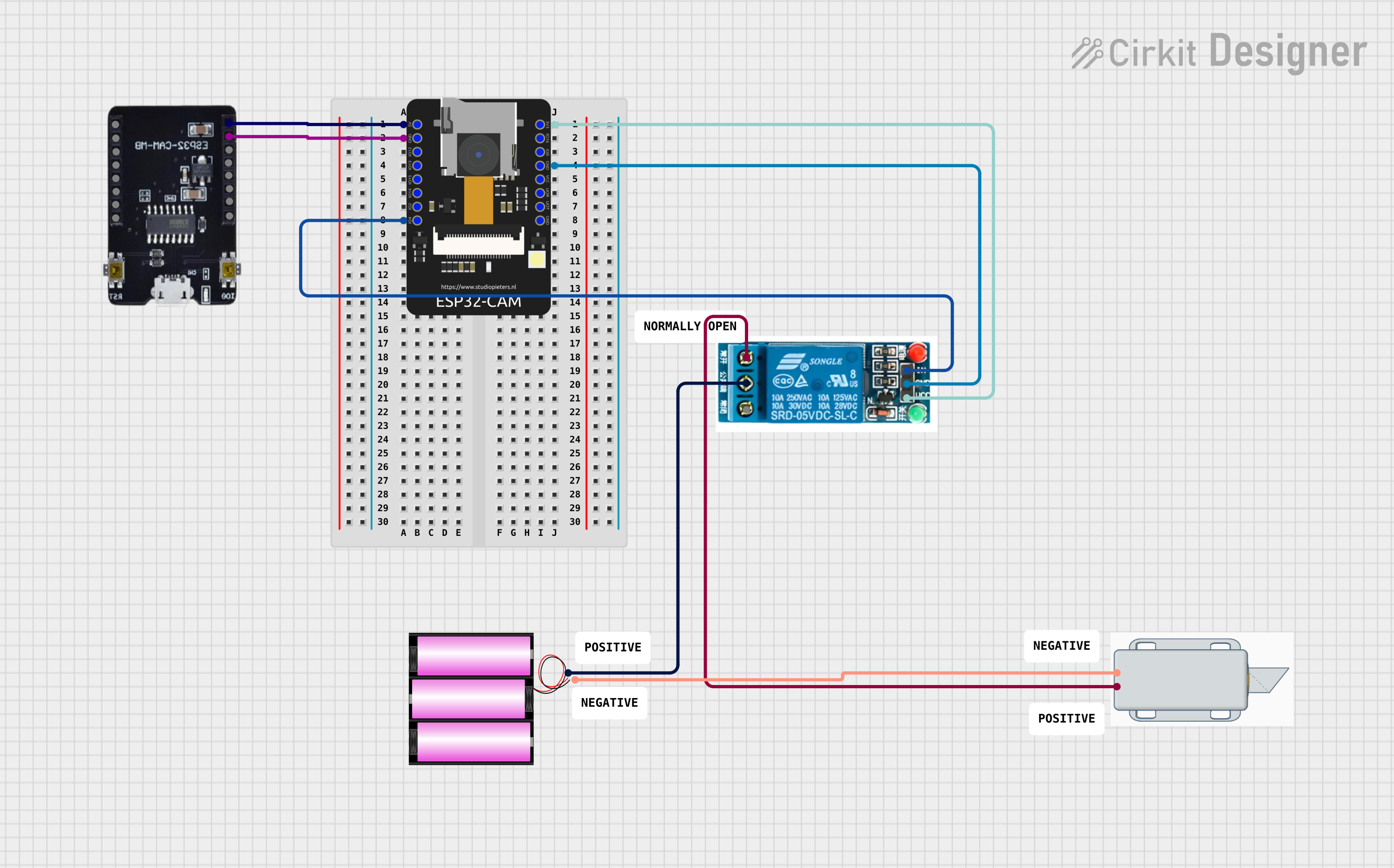
This circuit features an ESP32-CAM microcontroller configured to connect to a WiFi network and potentially perform facial recognition or other camera-related tasks. It controls a 5V relay, which in turn controls a 12V solenoid lock, allowing the lock to be engaged or disengaged based on the microcontroller's logic. The ESP32-CAM is powered by 5V, and the relay is used to switch the 12V power from the battery to the solenoid lock.
ESP32 CAM Wi-Fi Controlled Camera with FTDI Programmer

This circuit consists of an ESP32 CAM module connected to an FTDI Programmer for power and serial communication. The ESP32 CAM is programmed to capture images and stream them over WiFi, acting as a web server to provide live video feed.
ESP32-CAM Based Environmental Monitoring System with Gas Detection and Infrared Temperature Sensing
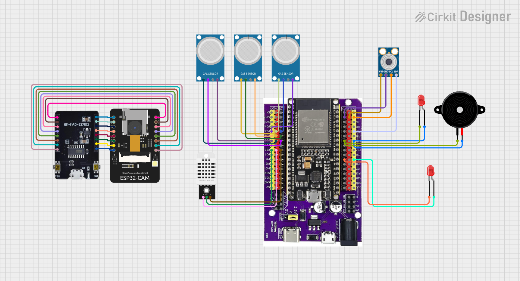
This is a multi-sensor environmental monitoring system with image capturing capabilities. It uses an ESP32 microcontroller to interface with gas, temperature, and humidity sensors, as well as an infrared temperature sensor and an ESP32-CAM module. The system can provide visual and audio alerts through connected LEDs and a piezo speaker.
ESP32 CAM Wi-Fi Controlled Camera with FTDI Programmer

This circuit consists of an ESP32 CAM module connected to an FTDI Programmer for power and serial communication. The ESP32 CAM is programmed to capture images and stream them over WiFi, acting as a web server to provide a live video feed.
Explore Projects Built with ESP32-CAM MB FLIP
ESP32-CAM Controlled Wi-Fi Smart Lock
This circuit features an ESP32-CAM microcontroller configured to connect to a WiFi network and potentially perform facial recognition or other camera-related tasks. It controls a 5V relay, which in turn controls a 12V solenoid lock, allowing the lock to be engaged or disengaged based on the microcontroller's logic. The ESP32-CAM is powered by 5V, and the relay is used to switch the 12V power from the battery to the solenoid lock.
ESP32 CAM Wi-Fi Controlled Camera with FTDI Programmer
This circuit consists of an ESP32 CAM module connected to an FTDI Programmer for power and serial communication. The ESP32 CAM is programmed to capture images and stream them over WiFi, acting as a web server to provide live video feed.
ESP32-CAM Based Environmental Monitoring System with Gas Detection and Infrared Temperature Sensing
This is a multi-sensor environmental monitoring system with image capturing capabilities. It uses an ESP32 microcontroller to interface with gas, temperature, and humidity sensors, as well as an infrared temperature sensor and an ESP32-CAM module. The system can provide visual and audio alerts through connected LEDs and a piezo speaker.
ESP32 CAM Wi-Fi Controlled Camera with FTDI Programmer
This circuit consists of an ESP32 CAM module connected to an FTDI Programmer for power and serial communication. The ESP32 CAM is programmed to capture images and stream them over WiFi, acting as a web server to provide a live video feed.
Common Applications
- Wireless video surveillance systems
- Smart home automation
- IoT devices with image recognition
- Remote-controlled robots with live video feed
- Face detection and recognition systems
Technical Specifications
Key Technical Details
| Parameter | Value |
|---|---|
| Microcontroller | ESP32-S (dual-core, 32-bit Xtensa LX6) |
| Flash Memory | 4 MB (SPI Flash) |
| Camera Sensor | OV2640 |
| Wi-Fi Standard | 802.11 b/g/n |
| Bluetooth Version | Bluetooth 4.2 (BLE + Classic) |
| Operating Voltage | 3.3V |
| Input Voltage (via USB) | 5V |
| GPIO Pins | 9 (configurable for various uses) |
| Power Consumption | ~160 mA (active), ~10 µA (deep sleep) |
| Dimensions | 40mm x 27mm |
Pin Configuration and Descriptions
| Pin Name | Pin Number | Description |
|---|---|---|
| GND | - | Ground |
| 3.3V | - | 3.3V power output |
| GPIO0 | 1 | Boot mode selection (connect to GND for flashing) |
| GPIO1 | 2 | UART TX (serial communication) |
| GPIO3 | 3 | UART RX (serial communication) |
| GPIO12 | 4 | Configurable GPIO |
| GPIO13 | 5 | Configurable GPIO |
| GPIO14 | 6 | Configurable GPIO |
| GPIO15 | 7 | Configurable GPIO |
| GPIO16 | 8 | Configurable GPIO |
| GPIO33 | 9 | Configurable GPIO |
| RESET | - | Reset button |
Usage Instructions
How to Use the ESP32-CAM MB FLIP in a Circuit
Powering the Board:
- Connect the ESP32-CAM MB FLIP to your computer via a USB cable. The onboard USB-to-serial adapter will handle power and programming.
- Ensure the input voltage is 5V when powering externally.
Flashing Firmware:
- Connect GPIO0 to GND to enable boot mode for flashing.
- Use the Arduino IDE or ESP-IDF to upload your code. Select the correct board (
AI-Thinker ESP32-CAM) and COM port in the IDE.
Connecting the Camera:
- The OV2640 camera module is pre-attached. Ensure it is securely connected to the board.
Using GPIO Pins:
- The GPIO pins can be used for sensors, actuators, or other peripherals. Note that some pins are shared with the camera and may have limited functionality.
Important Considerations and Best Practices
- Heat Management: The ESP32-CAM can get warm during operation. Ensure proper ventilation or use a heatsink if necessary.
- Power Supply: Use a stable 5V power source to avoid unexpected resets or malfunctions.
- GPIO Limitations: Avoid using GPIO0, GPIO2, and GPIO15 for general I/O, as they are used during boot.
- Antenna Placement: Ensure the onboard antenna is not obstructed for optimal Wi-Fi performance.
Example Code for Arduino UNO Integration
Below is an example of how to use the ESP32-CAM MB FLIP to stream video:
#include <WiFi.h>
#include <esp_camera.h>

// Replace with your network credentials
const char* ssid = "Your_SSID";
const char* password = "Your_PASSWORD";

void startCameraServer();

void setup() {
  Serial.begin(115200);
  WiFi.begin(ssid, password);

  // Wait for Wi-Fi connection
  while (WiFi.status() != WL_CONNECTED) {
    delay(500);
    Serial.print(".");
  }
  Serial.println("\nWiFi connected");

  // Start the camera server
  startCameraServer();
  Serial.println("Camera ready! Use the IP address below to view the stream:");
  Serial.println(WiFi.localIP());
}

void loop() {
  // Nothing to do here, the camera server runs in the background
}

// Function to initialize the camera and start the server
void startCameraServer() {
  camera_config_t config;
  config.ledc_channel = LEDC_CHANNEL_0;
  config.ledc_timer = LEDC_TIMER_0;
  config.pin_d0 = 5;
  config.pin_d1 = 18;
  config.pin_d2 = 19;
  config.pin_d3 = 21;
  config.pin_d4 = 36;
  config.pin_d5 = 39;
  config.pin_d6 = 34;
  config.pin_d7 = 35;
  config.pin_xclk = 0;
  config.pin_pclk = 22;
  config.pin_vsync = 25;
  config.pin_href = 23;
  config.pin_sscb_sda = 26;
  config.pin_sscb_scl = 27;
  config.pin_pwdn = -1;
  config.pin_reset = -1;
  config.xclk_freq_hz = 20000000;
  config.pixel_format = PIXFORMAT_JPEG;

  // Initialize the camera
  if (esp_camera_init(&config) != ESP_OK) {
    Serial.println("Camera init failed");
    return;
  }

  // Start the web server for video streaming
  Serial.println("Starting web server...");
  // Add your server initialization code here
}
Troubleshooting and FAQs
Common Issues
Camera Initialization Failed:
- Ensure the camera module is securely connected to the board.
- Verify that the correct camera model is selected in the code (
OV2640).
Wi-Fi Connection Issues:
- Double-check the SSID and password in your code.
- Ensure the ESP32-CAM is within range of your Wi-Fi router.
Board Not Detected by Computer:
- Verify that the USB cable supports data transfer (not just charging).
- Check the USB-to-serial adapter drivers on your computer.
Frequent Resets or Crashes:
- Use a stable 5V power source with sufficient current (at least 1A).
- Avoid using GPIO pins that conflict with the camera or boot process.
Tips for Troubleshooting
- Use the Serial Monitor in the Arduino IDE to view debug messages.
- If the board fails to boot, disconnect all peripherals and try again.
- Update the ESP32 core libraries in the Arduino IDE to the latest version.