Cirkit Designer Logo
Cirkit Designer
Your all-in-one circuit design IDE
Home / 
Component Documentation

How to Use Optical Interpreter: Examples, Pinouts, and Specs

Image of Optical Interpreter
Cirkit Designer LogoDesign with Optical Interpreter in Cirkit Designer

Introduction

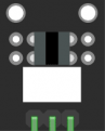
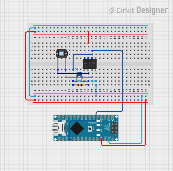
The Elegoo Optical Interpreter is an electronic component designed to convert optical signals into electrical signals. This module is commonly used in applications such as light intensity detection, optical data communication, and various forms of non-contact optical sensing. The device is particularly useful in robotics, automation, and interactive projects where light-based interaction is required.

Explore Projects Built with Optical Interpreter

Use Cirkit Designer to design, explore, and prototype these projects online. Some projects support real-time simulation. Click "Open Project" to start designing instantly!
Arduino Nano-Based Sign Language Interpreter with LCD Display and Flex Sensors
Image of Hand_Project: A project utilizing Optical Interpreter in a practical application
This circuit is a sign language interpreter system using an Arduino Nano, multiple flex resistors, and an LCD display. The flex resistors detect different hand gestures, which are read by the Arduino and displayed as corresponding messages on the LCD. The system is powered by a 9V battery and includes an I2C module for communication with the LCD.
Cirkit Designer LogoOpen Project in Cirkit Designer
ESP32-Based Eye Pressure Monitor with OLED Display and Multiple Sensors
Image of test4: A project utilizing Optical Interpreter in a practical application
This circuit is designed to monitor eye pressure and deformation using a photodiode, a TCRT 5000 IR sensor, and a VL53L0X time-of-flight distance sensor. The ESP32 microcontroller reads sensor data, processes it to determine eye pressure status, and displays the results on a 0.96" OLED screen. It includes safety features, sensor calibration, and the ability to display sensor values and eye pressure status in real-time.
Cirkit Designer LogoOpen Project in Cirkit Designer
Arduino Nano-Based Sign Language Interpreter with LCD Display and Flex Sensors
Image of Hand_Project: A project utilizing Optical Interpreter in a practical application
This circuit is a sign language interpreter system using an Arduino Nano, multiple flex resistors, and an I2C LCD display. The flex resistors act as sensors to detect different hand gestures, which are then processed by the Arduino to display corresponding messages on the LCD and control an LED based on the detected gesture.
Cirkit Designer LogoOpen Project in Cirkit Designer
Arduino Nano-Based Light Intensity Data Logger with Op-Amp Signal Conditioning
Image of TEST: A project utilizing Optical Interpreter in a practical application
This circuit is designed to detect light intensity using a photodiode and convert the signal into a readable voltage using a Transimpedance Amplifier (TIA) configuration with an LM358 Op-Amp. The resistor and capacitor form a feedback network for the TIA, which outputs a voltage proportional to the light intensity to the Arduino Nano's analog input (A0). The Arduino Nano is programmed to read this analog voltage, convert it to a digital value, and output the result over serial communication for monitoring or further processing.
Cirkit Designer LogoOpen Project in Cirkit Designer

Explore Projects Built with Optical Interpreter

Use Cirkit Designer to design, explore, and prototype these projects online. Some projects support real-time simulation. Click "Open Project" to start designing instantly!
Image of Hand_Project: A project utilizing Optical Interpreter in a practical application
Arduino Nano-Based Sign Language Interpreter with LCD Display and Flex Sensors
This circuit is a sign language interpreter system using an Arduino Nano, multiple flex resistors, and an LCD display. The flex resistors detect different hand gestures, which are read by the Arduino and displayed as corresponding messages on the LCD. The system is powered by a 9V battery and includes an I2C module for communication with the LCD.
Cirkit Designer LogoOpen Project in Cirkit Designer
Image of test4: A project utilizing Optical Interpreter in a practical application
ESP32-Based Eye Pressure Monitor with OLED Display and Multiple Sensors
This circuit is designed to monitor eye pressure and deformation using a photodiode, a TCRT 5000 IR sensor, and a VL53L0X time-of-flight distance sensor. The ESP32 microcontroller reads sensor data, processes it to determine eye pressure status, and displays the results on a 0.96" OLED screen. It includes safety features, sensor calibration, and the ability to display sensor values and eye pressure status in real-time.
Cirkit Designer LogoOpen Project in Cirkit Designer
Image of Hand_Project: A project utilizing Optical Interpreter in a practical application
Arduino Nano-Based Sign Language Interpreter with LCD Display and Flex Sensors
This circuit is a sign language interpreter system using an Arduino Nano, multiple flex resistors, and an I2C LCD display. The flex resistors act as sensors to detect different hand gestures, which are then processed by the Arduino to display corresponding messages on the LCD and control an LED based on the detected gesture.
Cirkit Designer LogoOpen Project in Cirkit Designer
Image of TEST: A project utilizing Optical Interpreter in a practical application
Arduino Nano-Based Light Intensity Data Logger with Op-Amp Signal Conditioning
This circuit is designed to detect light intensity using a photodiode and convert the signal into a readable voltage using a Transimpedance Amplifier (TIA) configuration with an LM358 Op-Amp. The resistor and capacitor form a feedback network for the TIA, which outputs a voltage proportional to the light intensity to the Arduino Nano's analog input (A0). The Arduino Nano is programmed to read this analog voltage, convert it to a digital value, and output the result over serial communication for monitoring or further processing.
Cirkit Designer LogoOpen Project in Cirkit Designer

Technical Specifications

General Features

  • Operating Voltage: 3.3V to 5V
  • Output Type: Analog and Digital
  • Sensitivity: Adjustable via onboard potentiometer
  • Response Time: < 20 ms
  • Operating Temperature Range: -10°C to +50°C

Pin Configuration and Descriptions

Pin Number Pin Name Description
1 VCC Power supply (3.3V to 5V)
2 GND Ground
3 AOUT Analog output signal
4 DOUT Digital output signal (threshold settable)

Usage Instructions

Connecting to a Circuit

  1. Power Connections: Connect the VCC pin to the power supply (3.3V to 5V) and the GND pin to the ground of your circuit.
  2. Signal Output: Connect the AOUT pin to an analog input on your microcontroller to read the intensity of the light. Connect the DOUT pin to a digital input if you wish to use the digital threshold feature.
  3. Adjusting Sensitivity: Use the onboard potentiometer to adjust the sensitivity of the optical interpreter. This will affect the threshold at which the digital output switches from LOW to HIGH.

Best Practices

  • Ensure that the power supply is within the specified range to prevent damage.
  • Avoid exposing the sensor to direct sunlight or strong artificial light to prevent saturation.
  • Use appropriate filtering or debouncing techniques when reading the digital output to avoid false triggering due to noise.

Example Code for Arduino UNO

This example demonstrates how to read the analog and digital outputs from the Elegoo Optical Interpreter using an Arduino UNO.

// Define the pins connected to the Optical Interpreter
const int analogPin = A0; // AOUT connected to A0
const int digitalPin = 2; // DOUT connected to digital pin 2

void setup() {
  // Initialize serial communication at 9600 baud rate
  Serial.begin(9600);
  
  // Set the digital pin as input
  pinMode(digitalPin, INPUT);
}

void loop() {
  // Read the analog value from the sensor
  int analogValue = analogRead(analogPin);
  
  // Read the digital value from the sensor
  int digitalValue = digitalRead(digitalPin);
  
  // Print the values to the serial monitor
  Serial.print("Analog Value: ");
  Serial.print(analogValue);
  Serial.print("\tDigital Value: ");
  Serial.println(digitalValue);
  
  // Wait for a short period before reading again
  delay(200);
}

Troubleshooting and FAQs

Common Issues

  • No Output Signal: Ensure that the power connections are correct and the power supply is within the specified range.
  • Inconsistent Readings: Check if the sensor is directly exposed to a strong light source or if there are fluctuations in the light intensity.
  • Digital Output Always High or Low: Adjust the sensitivity potentiometer to set the correct threshold for your application.

FAQs

Q: Can the Optical Interpreter be used with a 3.3V system? A: Yes, the module can operate at 3.3V, making it compatible with both 5V and 3.3V systems.

Q: How do I know if the sensor is saturated? A: If the analog output is consistently at its maximum value regardless of light changes, the sensor may be saturated. Reduce the light exposure or adjust the sensitivity.

Q: Is it possible to use multiple Optical Interpreters with one Arduino? A: Yes, you can connect multiple sensors to an Arduino, provided you have enough available pins and you manage each sensor's output separately in your code.

For further assistance or technical support, please contact Elegoo customer service or refer to the community forums for shared user experiences and solutions.