How to Use MD30C: Examples, Pinouts, and Specs
Introduction
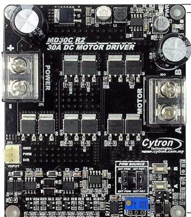
The MD30C, manufactured by Cytron, is a compact and efficient DC motor driver designed for controlling the speed and direction of DC motors. It features an integrated H-bridge circuit, enabling bidirectional motor control and precise speed modulation through Pulse Width Modulation (PWM). With its robust design and ease of use, the MD30C is ideal for applications in robotics, automation, and other motor control systems.
Explore Projects Built with MD30C


Explore Projects Built with MD30C
Common Applications
- Robotics: Driving wheels or robotic arms
- Conveyor systems in industrial automation
- Electric vehicles and carts
- DIY projects involving DC motor control
- Educational projects for learning motor control principles
Technical Specifications
The MD30C is designed to handle a wide range of DC motor control requirements. Below are its key technical specifications:
| Parameter | Value |
|---|---|
| Operating Voltage | 7V to 30V DC |
| Continuous Current | 30A |
| Peak Current | 80A (for 10 seconds) |
| Control Signal Voltage | 3.3V or 5V logic compatible |
| PWM Frequency Range | 1 kHz to 20 kHz |
| Motor Direction Control | Forward, Reverse, Brake, Stop |
| Protection Features | Overcurrent, Overtemperature |
| Dimensions | 84mm x 62mm x 28mm |
| Weight | 100g |
Pin Configuration and Descriptions
The MD30C has a straightforward pin layout for easy integration into your projects. Below is the pin configuration:
| Pin Name | Type | Description |
|---|---|---|
| VM | Power Input | Motor power supply (7V to 30V DC). Connect to the positive terminal of the power source. |
| GND | Power Ground | Ground connection. Connect to the negative terminal of the power source. |
| M+ | Motor Output | Positive terminal of the DC motor. |
| M- | Motor Output | Negative terminal of the DC motor. |
| PWM | Input Signal | PWM signal input for speed control. Accepts 3.3V or 5V logic levels. |
| DIR | Input Signal | Direction control input. High for forward, Low for reverse. |
| EN | Input Signal | Enable pin. High to enable the motor driver, Low to disable. |
| FG | Output Signal | Frequency generator output for motor speed feedback (optional). |
Usage Instructions
The MD30C is simple to use and can be integrated into a variety of motor control systems. Follow the steps below to use the MD30C in your project:
Connecting the MD30C
- Power Supply: Connect the VM pin to a DC power source (7V to 30V) and the GND pin to the ground of the power source.
- Motor Connection: Connect the DC motor terminals to the M+ and M- pins.
- Control Signals:
- Connect the PWM pin to a PWM-capable output pin of your microcontroller.
- Connect the DIR pin to a digital output pin of your microcontroller for direction control.
- Optionally, connect the EN pin to a digital output pin to enable or disable the motor driver.
- Feedback (Optional): If motor speed feedback is required, connect the FG pin to an input pin of your microcontroller.
Important Considerations
- Ensure the power supply voltage is within the specified range (7V to 30V).
- Use appropriate heat dissipation methods (e.g., heatsinks) if operating at high currents for extended periods.
- Avoid reversing the polarity of the power supply or motor connections to prevent damage.
- Use a fuse or circuit breaker for additional protection in high-current applications.
Example Code for Arduino UNO
Below is an example of how to control the MD30C using an Arduino UNO:
// Define pin connections
const int pwmPin = 9;  // PWM signal pin
const int dirPin = 8;  // Direction control pin
const int enPin = 7;   // Enable pin

void setup() {
  // Set pin modes
  pinMode(pwmPin, OUTPUT);
  pinMode(dirPin, OUTPUT);
  pinMode(enPin, OUTPUT);

  // Enable the motor driver
  digitalWrite(enPin, HIGH);
}

void loop() {
  // Set motor direction to forward
  digitalWrite(dirPin, HIGH);

  // Set motor speed to 50% using PWM
  analogWrite(pwmPin, 128);  // 128 is 50% duty cycle (0-255 range)

  delay(5000);  // Run motor for 5 seconds

  // Set motor direction to reverse
  digitalWrite(dirPin, LOW);

  // Set motor speed to 75% using PWM
  analogWrite(pwmPin, 192);  // 192 is 75% duty cycle

  delay(5000);  // Run motor for 5 seconds
}
Best Practices
- Use decoupling capacitors near the power input to reduce noise.
- Ensure proper grounding between the motor driver, microcontroller, and power source.
- Test the motor driver with a low-current motor before using it with high-current motors.
Troubleshooting and FAQs
Common Issues and Solutions
Motor Not Running
- Cause: EN pin is not set to HIGH.
- Solution: Ensure the EN pin is connected to a HIGH signal to enable the motor driver.
Motor Running in the Wrong Direction
- Cause: Incorrect DIR pin signal.
- Solution: Check the DIR pin connection and logic. High = Forward, Low = Reverse.
Overheating
- Cause: Prolonged operation at high currents without proper cooling.
- Solution: Use a heatsink or active cooling to dissipate heat.
No Response to PWM Signal
- Cause: Incorrect PWM frequency or signal level.
- Solution: Ensure the PWM signal is within the 1 kHz to 20 kHz range and uses 3.3V or 5V logic levels.
FAQs
Can the MD30C drive two motors simultaneously?
- No, the MD30C is designed to control a single DC motor.
What happens if the motor draws more than 30A continuously?
- The MD30C has overcurrent protection and will shut down to prevent damage.
Can I use the MD30C with a 3.3V microcontroller?
- Yes, the MD30C is compatible with both 3.3V and 5V logic levels.
Is the MD30C suitable for stepper motors?
- No, the MD30C is specifically designed for DC motors and is not compatible with stepper motors.
By following this documentation, you can effectively integrate the MD30C into your motor control projects.