How to Use OLED SSD1309: Examples, Pinouts, and Specs
Introduction
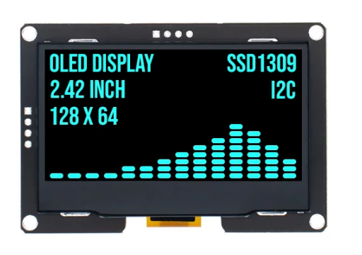
The OLED SSD1309 is a monochrome display driver designed for OLED screens. It supports a resolution of up to 128x64 pixels and offers communication via I2C or SPI interfaces. This component is widely used in applications requiring low power consumption, high contrast, and wide viewing angles. Its compact size and versatility make it ideal for embedded systems, wearable devices, and portable electronics.
Explore Projects Built with OLED SSD1309


Explore Projects Built with OLED SSD1309
Common Applications
- Wearable devices (e.g., smartwatches, fitness trackers)
- Portable electronics (e.g., handheld devices, calculators)
- Industrial control panels
- IoT devices and smart home displays
- Hobbyist and educational projects with microcontrollers (e.g., Arduino, Raspberry Pi)
Technical Specifications
Below are the key technical details of the OLED SSD1309:
| Parameter | Value |
|---|---|
| Resolution | 128x64 pixels |
| Communication Interface | I2C or SPI |
| Operating Voltage | 2.4V to 3.5V |
| Logic Voltage | 3.3V (compatible with 5V logic) |
| Current Consumption | ~10mA (typical) |
| Display Type | Monochrome OLED |
| Viewing Angle | >160° |
| Operating Temperature | -40°C to +85°C |
Pin Configuration (I2C Mode)
| Pin | Name | Description |
|---|---|---|
| 1 | GND | Ground connection |
| 2 | VCC | Power supply (2.4V to 3.5V) |
| 3 | SCL | Serial clock line for I2C communication |
| 4 | SDA | Serial data line for I2C communication |
| 5 | RES | Reset pin (active low) |
| 6 | DC | Data/Command control pin |
Pin Configuration (SPI Mode)
| Pin | Name | Description |
|---|---|---|
| 1 | GND | Ground connection |
| 2 | VCC | Power supply (2.4V to 3.5V) |
| 3 | SCK | Serial clock line for SPI communication |
| 4 | MOSI | Master Out Slave In (data input for SPI) |
| 5 | RES | Reset pin (active low) |
| 6 | DC | Data/Command control pin |
| 7 | CS | Chip Select (active low) |
Usage Instructions
Connecting the SSD1309 to an Arduino UNO (I2C Mode)
Wiring: Connect the OLED SSD1309 to the Arduino UNO as follows:
- GND → GND
- VCC → 3.3V or 5V (depending on your module)
- SCL → A5 (Arduino I2C clock pin)
- SDA → A4 (Arduino I2C data pin)
- RES → Any digital pin (e.g., D8)
- DC → Any digital pin (e.g., D9)
Install Required Libraries:
- Install the
Adafruit_GFXandAdafruit_SSD1306libraries via the Arduino Library Manager.
- Install the
Example Code: Below is an example sketch to display "Hello, World!" on the SSD1309:
#include <Wire.h>
#include <Adafruit_GFX.h>
#include <Adafruit_SSD1306.h>

// Define OLED display width and height
#define SCREEN_WIDTH 128
#define SCREEN_HEIGHT 64

// Create an SSD1306 object (I2C address 0x3C is common for SSD1309)
Adafruit_SSD1306 display(SCREEN_WIDTH, SCREEN_HEIGHT, &Wire, -1);

void setup() {
  // Initialize the display
  if (!display.begin(SSD1306_I2C_ADDRESS, 0x3C)) {
    // If initialization fails, print an error message
    Serial.println(F("SSD1309 initialization failed!"));
    for (;;); // Halt execution
  }

  // Clear the display buffer
  display.clearDisplay();

  // Set text size and color
  display.setTextSize(1); // Normal text size
  display.setTextColor(SSD1306_WHITE);

  // Display "Hello, World!" on the screen
  display.setCursor(0, 0); // Set cursor to top-left corner
  display.println(F("Hello, World!"));

  // Update the display with the buffer content
  display.display();
}

void loop() {
  // Nothing to do here
}
Important Considerations
- Voltage Levels: Ensure the OLED module is compatible with your microcontroller's voltage levels. Most SSD1309 modules support 3.3V logic but can tolerate 5V logic.
- Pull-Up Resistors: For I2C communication, ensure pull-up resistors (typically 4.7kΩ) are present on the SDA and SCL lines. Some modules include these resistors by default.
- Reset Pin: The RES pin must be properly initialized during startup. If not connected, the display may not function correctly.
Troubleshooting and FAQs
Common Issues
Display Not Turning On:
- Verify the power supply voltage (2.4V to 3.5V).
- Check all connections for loose wires or incorrect pin mapping.
- Ensure the RES pin is properly connected or initialized in the code.
No Output on the Screen:
- Confirm the I2C address (default is 0x3C). Use an I2C scanner sketch to detect the address.
- Ensure the correct libraries (
Adafruit_GFXandAdafruit_SSD1306) are installed and up to date.
Flickering or Artifacts:
- Check for noise on the power supply lines.
- Ensure proper grounding between the OLED module and the microcontroller.
Partial or Distorted Display:
- Verify the resolution settings in the code (128x64 for SSD1309).
- Ensure the correct communication protocol (I2C or SPI) is selected in the code.
FAQs
Q: Can the SSD1309 display grayscale?
A: No, the SSD1309 is a monochrome display driver and supports only black and white pixels.
Q: What is the maximum refresh rate of the SSD1309?
A: The refresh rate depends on the communication speed and the microcontroller but typically ranges from 60Hz to 100Hz.
Q: Can I use the SSD1309 with a Raspberry Pi?
A: Yes, the SSD1309 is compatible with Raspberry Pi via I2C or SPI. Use libraries like luma.oled for Python-based development.
Q: How do I switch between I2C and SPI modes?
A: Most SSD1309 modules have solder jumpers or configuration pins to select the communication mode. Refer to your module's datasheet for details.