
How to Use Zener Diode: Examples, Pinouts, and Specs
 Design with Zener Diode in Cirkit Designer
Introduction
A Zener diode is a type of semiconductor device that allows current to flow in the reverse direction when a specific reverse voltage, known as the Zener voltage, is reached. Unlike regular diodes, which block reverse current, Zener diodes are designed to operate in the breakdown region without damage. This unique property makes them ideal for applications such as voltage regulation, overvoltage protection, and waveform clipping.
Explore Projects Built with Zener Diode
 Open Project in Cirkit Designer
 Open Project in Cirkit Designer
 Open Project in Cirkit Designer
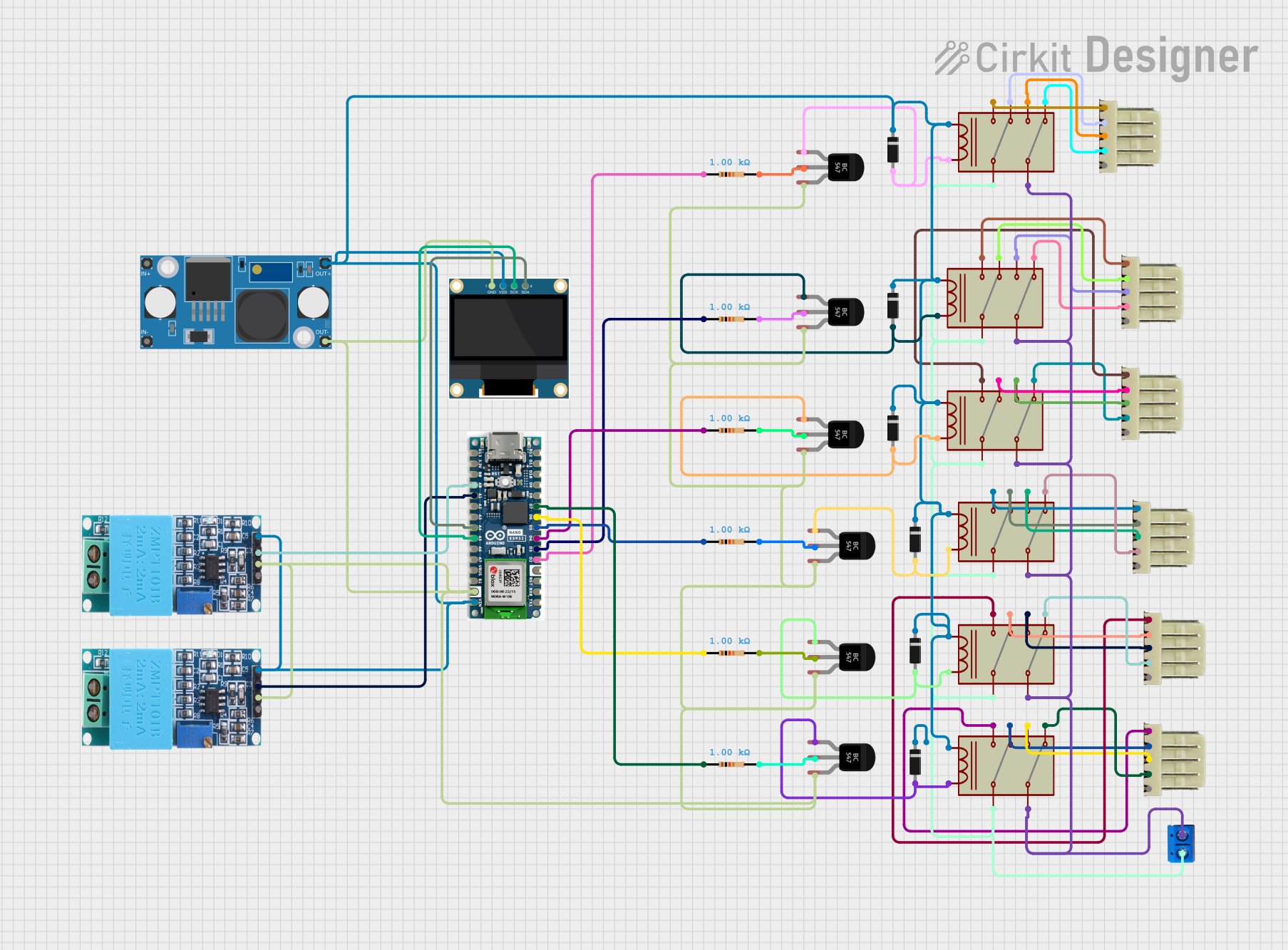 Open Project in Cirkit Designer
Explore Projects Built with Zener Diode
Open Project in Cirkit DesignerOpen Project in Cirkit DesignerOpen Project in Cirkit DesignerOpen Project in Cirkit DesignerCommon Applications and Use Cases
- Voltage regulation in power supplies
- Overvoltage protection for sensitive components
- Reference voltage generation in precision circuits
- Signal clipping and waveform shaping
Technical Specifications
Below are the general technical specifications for a Zener diode. Note that specific values depend on the model and manufacturer.
Key Technical Details
- Zener Voltage (Vz): Typically ranges from 2.4V to 200V
- Power Dissipation (P): Commonly 0.25W, 0.5W, or 1W
- Maximum Reverse Current (Ir): Typically in the microampere range
- Temperature Coefficient: Varies with Zener voltage, typically ±0.05%/°C
- Forward Voltage (Vf): Approximately 0.7V (similar to a standard diode)
Pin Configuration and Descriptions
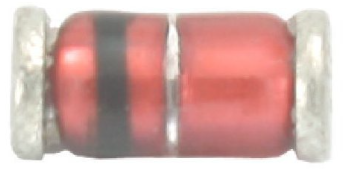
Zener diodes typically have two terminals: Anode and Cathode. The cathode is marked with a band on the diode body.
| Pin Name | Description | Symbol |
|---|---|---|
| Anode | Positive terminal of the diode | A |
| Cathode | Negative terminal, marked with a band | K |
Usage Instructions
How to Use the Zener Diode in a Circuit
Voltage Regulation:
- Connect the Zener diode in reverse bias (cathode to positive voltage, anode to ground).
- Place a current-limiting resistor in series with the Zener diode to prevent excessive current.
- The Zener diode will maintain a stable voltage across its terminals equal to its Zener voltage (Vz).
Overvoltage Protection:
- Place the Zener diode across the load in reverse bias.
- When the input voltage exceeds the Zener voltage, the diode conducts and clamps the voltage to the Zener voltage.
Reference Voltage:
- Use the Zener diode in reverse bias to provide a stable reference voltage for other circuit components.
Important Considerations and Best Practices
- Always use a current-limiting resistor to prevent the Zener diode from exceeding its maximum power dissipation.
- Choose a Zener diode with a Zener voltage close to the desired regulated voltage.
- Ensure the power rating of the Zener diode is sufficient for the application.
- Avoid operating the Zener diode at temperatures beyond its specified range to prevent thermal runaway.
Example: Using a Zener Diode with an Arduino UNO
Below is an example of using a Zener diode for voltage regulation in a circuit connected to an Arduino UNO.
// Example: Reading a regulated voltage using a Zener diode
// This code assumes a Zener diode is used to regulate voltage to 5V.

const int analogPin = A0; // Pin connected to the Zener diode output
float voltage = 0.0;

void setup() {
  Serial.begin(9600); // Initialize serial communication
}

void loop() {
  int sensorValue = analogRead(analogPin); // Read the analog input
  voltage = sensorValue * (5.0 / 1023.0);  // Convert to voltage
  Serial.print("Regulated Voltage: ");
  Serial.print(voltage);
  Serial.println(" V");
  delay(1000); // Wait for 1 second
}
Circuit Setup:
- Connect the Zener diode in reverse bias across the input voltage.
- Use a resistor in series with the Zener diode to limit current.
- Connect the output of the Zener diode to the Arduino analog pin (A0).
Troubleshooting and FAQs
Common Issues and Solutions
Zener Diode Overheating:
- Cause: Excessive current through the diode.
- Solution: Use a higher-value current-limiting resistor or a Zener diode with a higher power rating.
Voltage Not Regulated Properly:
- Cause: Input voltage is below the Zener voltage.
- Solution: Ensure the input voltage is at least 1-2V higher than the Zener voltage.
No Voltage Across the Zener Diode:
- Cause: Incorrect polarity or faulty connections.
- Solution: Verify the cathode is connected to the positive voltage and the anode to ground.
Arduino Reading Incorrect Voltage:
- Cause: Incorrect resistor value or poor connections.
- Solution: Double-check the resistor value and ensure all connections are secure.
FAQs
Q: Can I use a Zener diode without a resistor?
A: No, a current-limiting resistor is essential to prevent the Zener diode from exceeding its maximum power dissipation.
Q: How do I select the right Zener diode for my application?
A: Choose a Zener diode with a Zener voltage close to your desired regulated voltage and ensure its power rating is sufficient for the expected current.
Q: Can Zener diodes be used in AC circuits?
A: Yes, but they are typically used with rectifiers or in combination with other components to handle AC signals effectively.
Q: What happens if the input voltage is too high?
A: The Zener diode will conduct more current, potentially overheating. Use a resistor to limit current and ensure the diode's power rating is not exceeded.