
How to Use Protoboard 20x80mm: Examples, Pinouts, and Specs
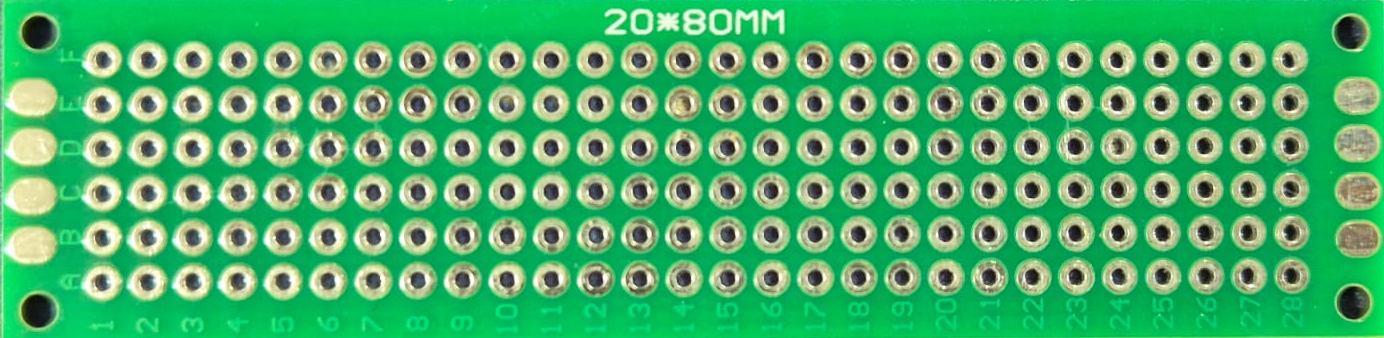
 Design with Protoboard 20x80mm in Cirkit Designer
Introduction
- The Protoboard 20x80mm, also known as a breadboard, is a compact and reusable platform designed for building and testing electronic circuits without the need for soldering. Its 20x80mm dimensions make it ideal for small-scale projects and prototyping.
- Common applications include:
- Rapid prototyping of electronic circuits.
- Educational purposes for learning circuit design.
- Temporary circuit assembly for testing and debugging.
- Small DIY electronics projects.
Explore Projects Built with Protoboard 20x80mm
 Open Project in Cirkit Designer
 Open Project in Cirkit Designer
 Open Project in Cirkit Designer
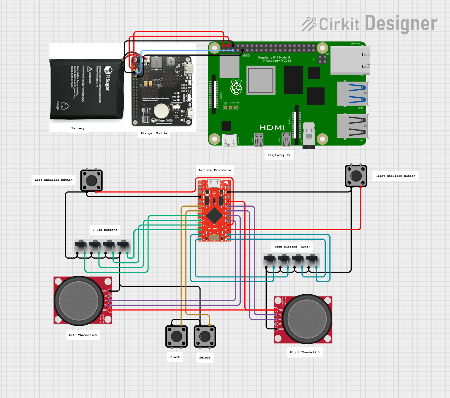 Open Project in Cirkit Designer
Explore Projects Built with Protoboard 20x80mm
Open Project in Cirkit DesignerOpen Project in Cirkit DesignerOpen Project in Cirkit DesignerOpen Project in Cirkit DesignerTechnical Specifications
- Dimensions: 20mm x 80mm
- Material: ABS plastic body with nickel-plated phosphor bronze contacts.
- Contact Points: Typically 170 tie points (may vary slightly by manufacturer).
- Voltage Rating: Up to 36V DC.
- Current Rating: Up to 1A per contact.
- Compatibility: Supports standard 22-28 AWG wires and most through-hole components.
Pin Configuration and Descriptions
The protoboard does not have traditional "pins" but instead features rows and columns of contact points. Below is a description of its layout:
| Section | Description |
|---|---|
| Power Rails | Two horizontal rows at the top and bottom for power distribution (optional). |
| Terminal Strips | Vertical columns of connected tie points for component connections. |
| Adhesive Backing | Some models include adhesive backing for mounting on surfaces. |
Usage Instructions
How to Use the Protoboard in a Circuit
Power Distribution:
- Use the horizontal power rails (if available) to distribute power (e.g., 5V and GND).
- Connect a power source, such as a battery or a regulated power supply, to the rails.
Component Placement:
- Insert components (e.g., resistors, LEDs, ICs) into the vertical terminal strips.
- Ensure that each leg of a component is placed in a separate row to avoid short circuits.
Wiring:
- Use jumper wires to connect components across different rows or sections.
- Ensure proper insulation and avoid overlapping wires to maintain clarity.
Testing:
- Once the circuit is assembled, connect the power source and test the functionality.
- Use a multimeter to verify connections and measure voltages or currents as needed.
Important Considerations and Best Practices
- Avoid exceeding the voltage and current ratings to prevent damage to the protoboard or components.
- Use wires of appropriate gauge (22-28 AWG) for reliable connections.
- Keep the layout organized to simplify troubleshooting.
- Avoid excessive force when inserting or removing components to prevent damaging the contact points.
- If using an Arduino UNO or similar microcontroller, connect its pins to the protoboard using jumper wires for easy prototyping.
Example: Connecting an LED to an Arduino UNO
Below is an example of how to connect an LED to an Arduino UNO using the protoboard:
// Example: Blink an LED using Arduino UNO and Protoboard

// Define the pin connected to the LED
const int ledPin = 13;

void setup() {
  pinMode(ledPin, OUTPUT); // Set the LED pin as an output
}

void loop() {
  digitalWrite(ledPin, HIGH); // Turn the LED on
  delay(1000);                // Wait for 1 second
  digitalWrite(ledPin, LOW);  // Turn the LED off
  delay(1000);                // Wait for 1 second
}
Connections:
- Connect the Arduino UNO's GND pin to the protoboard's ground rail.
- Connect the Arduino UNO's pin 13 to one leg of the LED (via a 220-ohm resistor).
- Connect the other leg of the LED to the ground rail.
Troubleshooting and FAQs
Common Issues Users Might Face
Loose Connections:
- Problem: Components or wires are not making proper contact.
- Solution: Ensure wires and component leads are fully inserted into the tie points.
Short Circuits:
- Problem: Adjacent rows or columns are unintentionally connected.
- Solution: Double-check the layout and ensure no unintended connections exist.
Overheating:
- Problem: Exceeding the current rating causes overheating of contacts.
- Solution: Use components and power sources within the protoboard's rated limits.
Power Rail Misuse:
- Problem: Incorrectly connecting power and ground to the same rail.
- Solution: Clearly label the power and ground rails to avoid confusion.
FAQs
Q: Can I solder components onto the protoboard?
A: No, the protoboard is designed for temporary, solder-free connections. For permanent circuits, use a solderable perfboard or PCB.Q: What is the maximum wire gauge supported?
A: The protoboard typically supports 22-28 AWG wires.Q: Can I use the protoboard for high-frequency circuits?
A: While possible, protoboards are not ideal for high-frequency circuits due to potential signal interference and parasitic capacitance.Q: How do I clean the protoboard?
A: Use a soft brush or compressed air to remove dust and debris. Avoid using liquids that may damage the contacts.
By following this documentation, users can effectively utilize the Protoboard 20x80mm for their electronic prototyping needs.