How to Use Buzzer Passive: Examples, Pinouts, and Specs
Introduction
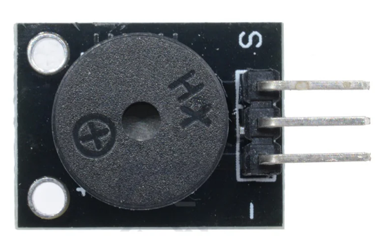
A passive buzzer is an electronic component that produces sound when an alternating current (AC) voltage is applied. Unlike an active buzzer, it does not have an internal oscillator and requires an external signal, such as a square wave, to generate sound. Passive buzzers are widely used in applications where sound notifications or alarms are required, such as in electronic devices, home appliances, and security systems.
Explore Projects Built with Buzzer Passive
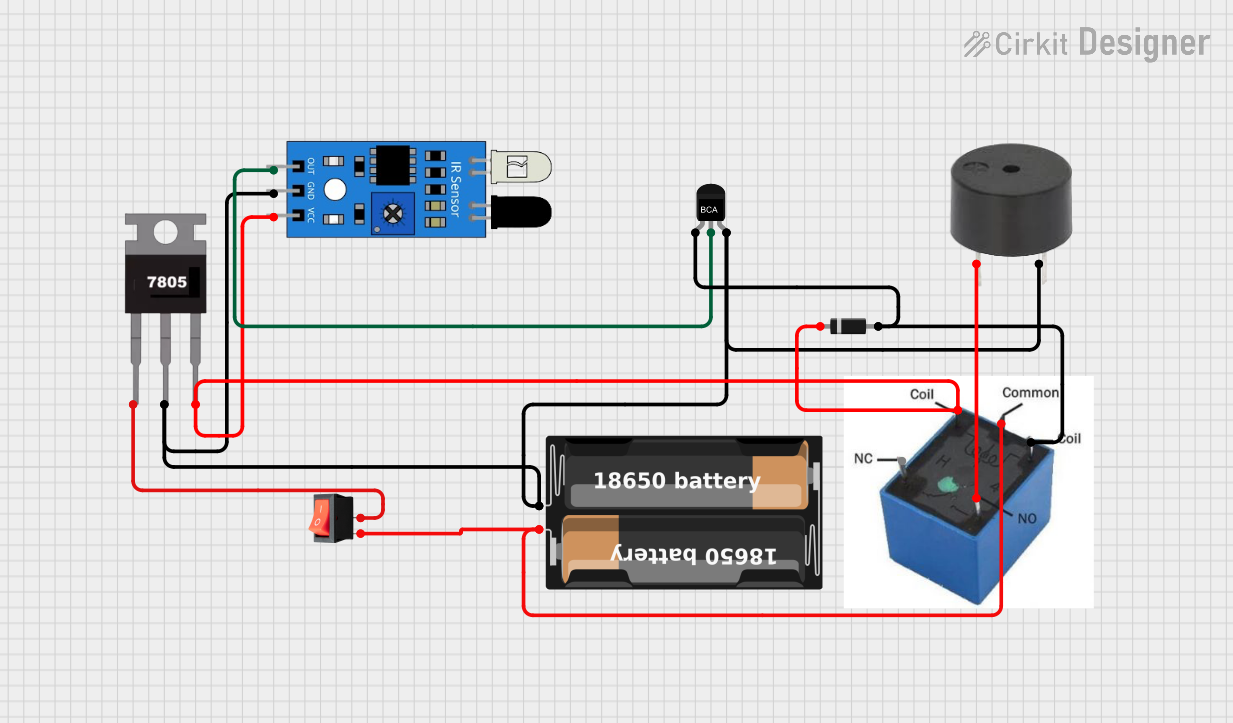
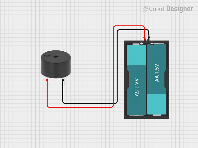
Explore Projects Built with Buzzer Passive
Common Applications:
- Alarms and notifications in electronic devices
- Sound indicators in home appliances
- Security systems and warning signals
- Educational and DIY electronics projects
Technical Specifications
Key Technical Details:
- Operating Voltage: 3V to 12V (typical: 5V)
- Operating Current: 10mA to 30mA
- Sound Frequency Range: 1kHz to 5kHz (optimal: ~2kHz)
- Sound Pressure Level (SPL): ~85dB at 10cm (varies by model)
- Dimensions: Varies (commonly 12mm diameter)
- Type: Passive (requires external signal)
Pin Configuration and Descriptions:
| Pin Name | Description |
|---|---|
| Positive (+) | Connect to the positive terminal of the power supply or signal source. |
| Negative (-) | Connect to the ground (GND) of the circuit. |
Usage Instructions
How to Use the Passive Buzzer in a Circuit:
Connect the Buzzer:
- Connect the positive pin of the buzzer to the output pin of a microcontroller or signal generator.
- Connect the negative pin of the buzzer to the ground (GND) of the circuit.
Generate a Signal:
- Use a microcontroller (e.g., Arduino) or an external oscillator to generate a square wave signal.
- The frequency of the square wave determines the pitch of the sound produced by the buzzer.
Power the Circuit:
- Ensure the operating voltage is within the buzzer's specified range (typically 3V to 12V).
Important Considerations:
- Signal Frequency: The sound produced depends on the frequency of the input signal. For optimal sound, use a frequency around 2kHz.
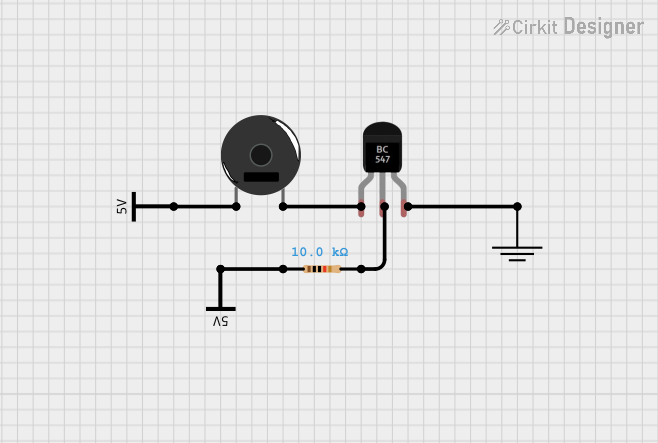
- Current Limiting: If the buzzer draws more current than the microcontroller pin can supply, use a transistor or MOSFET as a driver.
- Polarity: Ensure correct polarity when connecting the buzzer to avoid damage.
Example: Using a Passive Buzzer with Arduino UNO
Below is an example of how to use a passive buzzer with an Arduino UNO to generate a tone.
// Example: Generate a tone using a passive buzzer with Arduino UNO

// Define the pin connected to the buzzer
const int buzzerPin = 9;

void setup() {
  // Set the buzzer pin as an output
  pinMode(buzzerPin, OUTPUT);
}

void loop() {
  // Generate a 2kHz tone for 500ms
  tone(buzzerPin, 2000, 500); // 2000 Hz frequency, 500 ms duration
  delay(1000);                // Wait for 1 second

  // Generate a 1kHz tone for 500ms
  tone(buzzerPin, 1000, 500); // 1000 Hz frequency, 500 ms duration
  delay(1000);                // Wait for 1 second
}
Notes:
- The
tone()function generates a square wave signal on the specified pin. - Use the
noTone()function to stop the sound if needed.
Troubleshooting and FAQs
Common Issues and Solutions:
No Sound from the Buzzer:
- Cause: Incorrect signal frequency or insufficient voltage.
- Solution: Ensure the input signal is a square wave within the buzzer's frequency range (1kHz to 5kHz). Verify the power supply voltage.
Low or Distorted Sound:
- Cause: Insufficient current or incorrect signal amplitude.
- Solution: Use a transistor or MOSFET to drive the buzzer if the microcontroller cannot supply enough current.
Buzzer Not Working at All:
- Cause: Incorrect polarity or damaged component.
- Solution: Check the connections and ensure the positive and negative pins are correctly connected. Replace the buzzer if it is damaged.
Interference with Other Components:
- Cause: Noise from the buzzer affecting nearby components.
- Solution: Add a decoupling capacitor (e.g., 0.1µF) across the power supply pins to reduce noise.
FAQs:
Q: Can I use a passive buzzer without a microcontroller?
- A: Yes, you can use an external oscillator circuit or a 555 timer IC to generate the required signal.
Q: What is the difference between a passive and an active buzzer?
- A: A passive buzzer requires an external signal to produce sound, while an active buzzer has a built-in oscillator and only needs a DC voltage to operate.
Q: How do I adjust the sound frequency?
- A: Change the frequency of the input signal (e.g., using the
tone()function in Arduino).
- A: Change the frequency of the input signal (e.g., using the
Q: Can I use a passive buzzer with a Raspberry Pi?
- A: Yes, but since the Raspberry Pi does not have a built-in
tone()function, you will need to use a library or external circuit to generate the signal.
- A: Yes, but since the Raspberry Pi does not have a built-in
By following this documentation, you can effectively use a passive buzzer in your projects and troubleshoot common issues.