How to Use 74HC32: Examples, Pinouts, and Specs

Introduction
The 74HC32 is a logic gate integrated circuit (IC) that contains four independent 2-input OR gates. It is part of the 74HC family, which is a range of high-speed CMOS (Complementary Metal-Oxide-Semiconductor) logic chips. The OR gate is a digital logic gate that outputs a HIGH level (1) if one or more of its inputs are HIGH. The 74HC32 is commonly used in digital circuits where a logical addition function is required.
Explore Projects Built with 74HC32

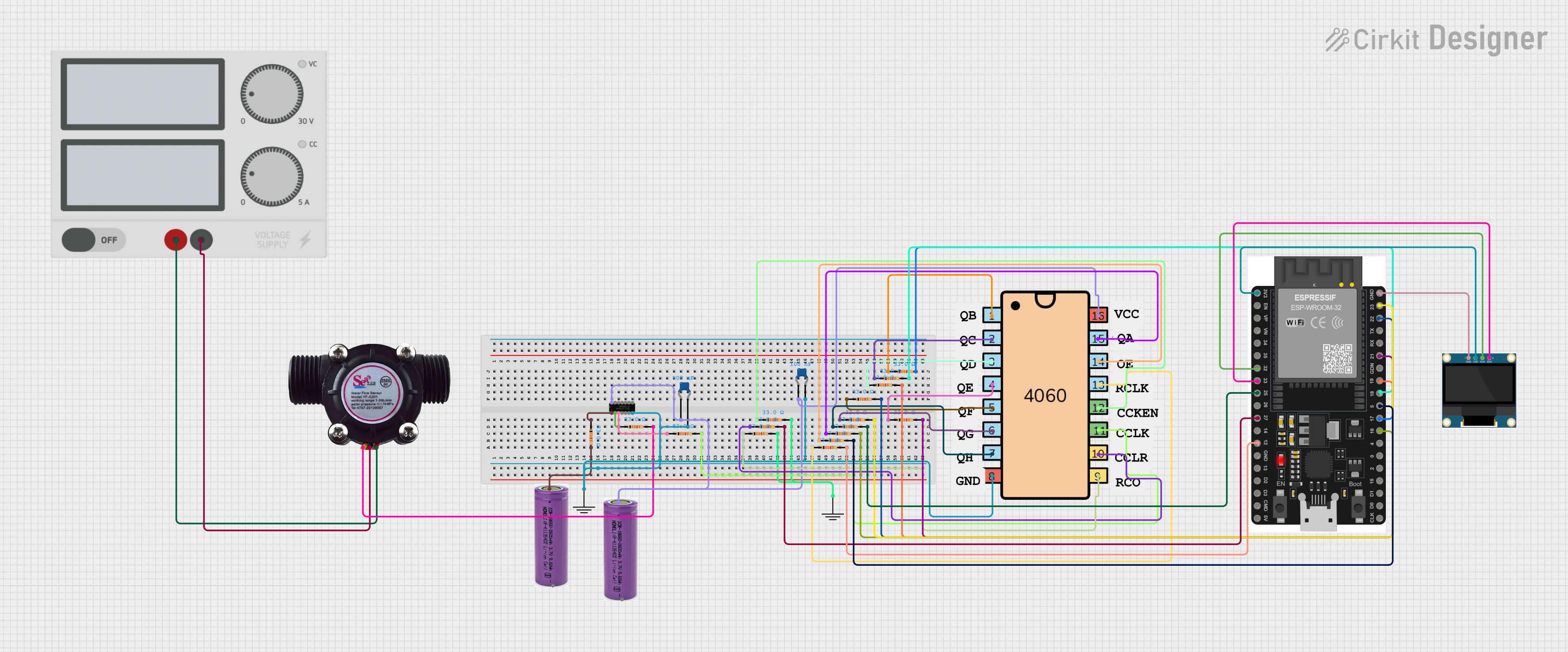

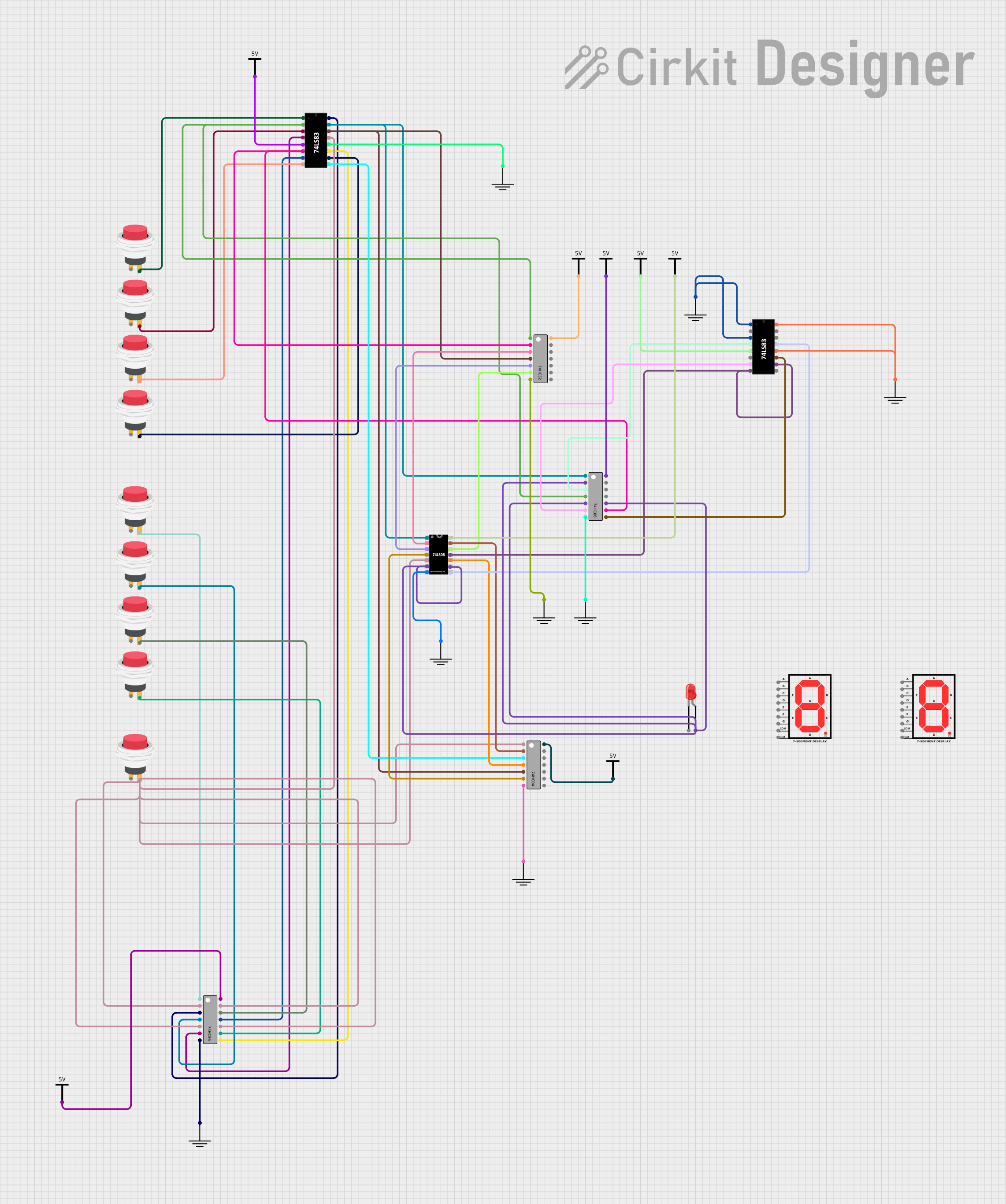
Explore Projects Built with 74HC32
Common Applications and Use Cases
- Digital logic circuits
- Signal gating
- Function generation
- Alarm systems
- Input signal buffering
Technical Specifications
Key Technical Details
- Supply Voltage (Vcc): 2V to 6V
- Input Voltage (Vin): 0V to Vcc
- Output Voltage (Vout): 0V to Vcc
- High-Level Input Voltage (VIH): Minimum 2V
- Low-Level Input Voltage (VIL): Maximum 0.8V
- High-Level Output Current (IOH): -5.2 mA (max)
- Low-Level Output Current (IOL): 5.2 mA (max)
- Propagation Delay Time: Approx. 8ns (Vcc = 4.5V, CL = 15pF)
- Operating Temperature Range: -40°C to +125°C
Pin Configuration and Descriptions
| Pin Number | Pin Name | Description |
|---|---|---|
| 1 | 1A | Input A for the first OR gate |
| 2 | 1B | Input B for the first OR gate |
| 3 | 1Y | Output for the first OR gate |
| 4 | 2A | Input A for the second OR gate |
| 5 | 2B | Input B for the second OR gate |
| 6 | 2Y | Output for the second OR gate |
| 7 | GND | Ground (0V) |
| 8 | 3A | Input A for the third OR gate |
| 9 | 3B | Input B for the third OR gate |
| 10 | 3Y | Output for the third OR gate |
| 11 | 4A | Input A for the fourth OR gate |
| 12 | 4B | Input B for the fourth OR gate |
| 13 | 4Y | Output for the fourth OR gate |
| 14 | Vcc | Positive supply voltage |
Usage Instructions
How to Use the 74HC32 in a Circuit
Power Supply Connection: Connect the Vcc pin (pin 14) to a positive supply voltage within the range of 2V to 6V. Connect the GND pin (pin 7) to the ground of the circuit.
Input Connection: Connect the inputs (1A, 1B, 2A, 2B, 3A, 3B, 4A, 4B) to the signals you wish to OR together. These can be from other logic gates, switches, or any digital signal source.
Output Connection: The outputs (1Y, 2Y, 3Y, 4Y) will provide the result of the OR operation. Connect these to the next stage of your circuit, such as input to another logic gate, LED for indication, or a microcontroller pin.
Important Considerations and Best Practices
- Ensure that the supply voltage does not exceed the maximum rating of 6V to prevent damage to the IC.
- Inputs should not be left floating; they should be connected to a HIGH or LOW voltage level.
- Decoupling capacitors (typically 0.1 µF) should be placed close to the Vcc pin to filter out noise.
- Avoid exceeding the maximum current ratings for both the input and output pins.
Troubleshooting and FAQs
Common Issues Users Might Face
- Outputs not behaving as expected: Ensure that all inputs are connected properly and are receiving the correct logic levels. Check for any short circuits or open connections.
- IC getting hot or damaged: Verify that the supply voltage is within the specified range and that the current limits are not being exceeded.
Solutions and Tips for Troubleshooting
- Check Supply Voltage: Use a multimeter to confirm that the supply voltage is within the recommended range.
- Inspect Connections: Double-check all connections, including power supply and ground, for any soldering errors or loose wires.
- Input Levels: Ensure that input signals are within the specified HIGH and LOW voltage levels.
FAQs
Q: Can I replace the 74HC32 with another OR gate IC? A: Yes, you can replace it with another OR gate IC, but make sure to check the pin configuration and electrical characteristics as they may differ.
Q: What happens if I exceed the recommended voltage or current ratings? A: Exceeding the voltage or current ratings can lead to malfunction or permanent damage to the IC.
Q: Can I use the 74HC32 at a temperature below 0°C or above 70°C? A: The 74HC32 is rated for operation between -40°C and +125°C, so it can be used within this temperature range.
Example Code for Arduino UNO
// Example code to demonstrate the use of 74HC32 with an Arduino UNO

const int inputPinA = 2; // Connect to 1A on the 74HC32
const int inputPinB = 3; // Connect to 1B on the 74HC32
const int outputPin = 4; // Connect to 1Y on the 74HC32

void setup() {
  pinMode(inputPinA, OUTPUT);
  pinMode(inputPinB, OUTPUT);
  pinMode(outputPin, INPUT);
}

void loop() {
  // Set both inputs to LOW
  digitalWrite(inputPinA, LOW);
  digitalWrite(inputPinB, LOW);
  delay(1000); // Wait for 1 second

  // Set input A to HIGH, B remains LOW
  digitalWrite(inputPinA, HIGH);
  delay(1000); // The output should now be HIGH

  // Set input B to HIGH, A remains HIGH
  digitalWrite(inputPinB, HIGH);
  delay(1000); // The output should remain HIGH

  // Read the output of the OR gate
  int orResult = digitalRead(outputPin);

  // Print the result to the Serial Monitor
  Serial.print("OR Gate Result: ");
  Serial.println(orResult); // Should print 1 when either A or B is HIGH
}
Remember to keep the code comments concise and within the 80-character line length limit. This example demonstrates a simple use case of the 74HC32 OR gate with an Arduino UNO. The actual implementation in a real-world application would depend on the specific requirements of the project.