How to Use Adafruit FunHouse: Examples, Pinouts, and Specs
Introduction
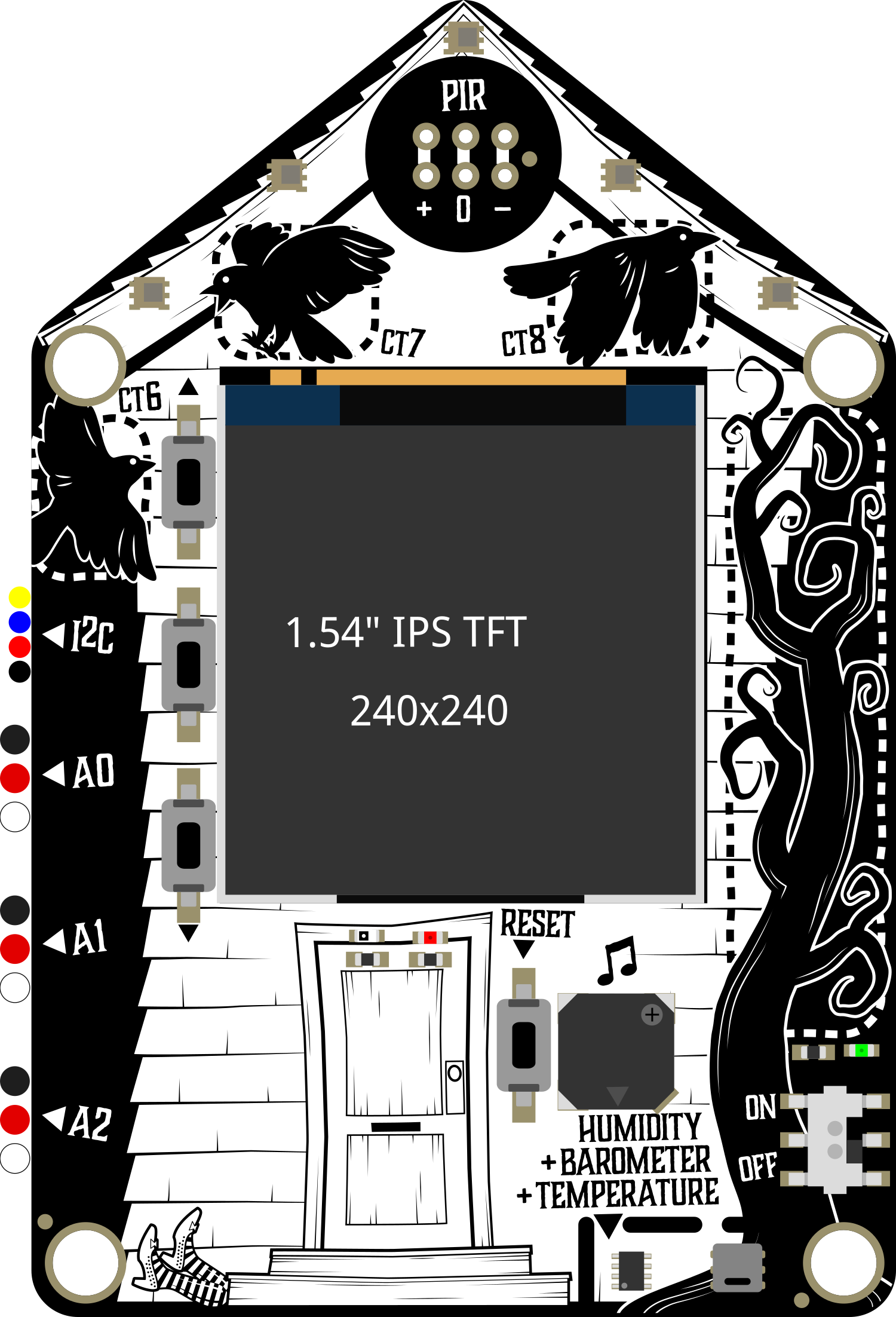
The Adafruit FunHouse is an innovative development board designed for creating smart home projects. It is built around the powerful ESP32 microcontroller and is equipped with a variety of sensors and actuators, making it an ideal platform for IoT applications. The FunHouse is particularly user-friendly, with a capacitive touch display for interactive projects and connectors that simplify the addition of extra modules.
Explore Projects Built with Adafruit FunHouse
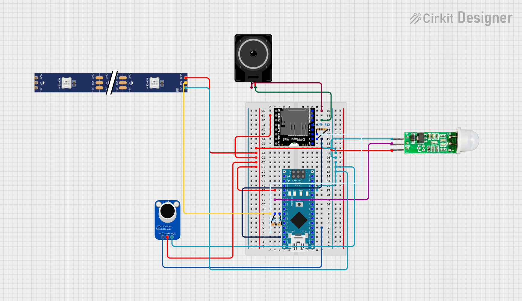
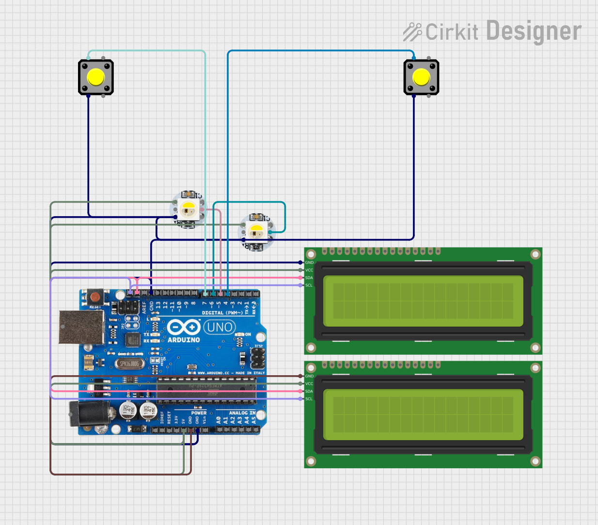
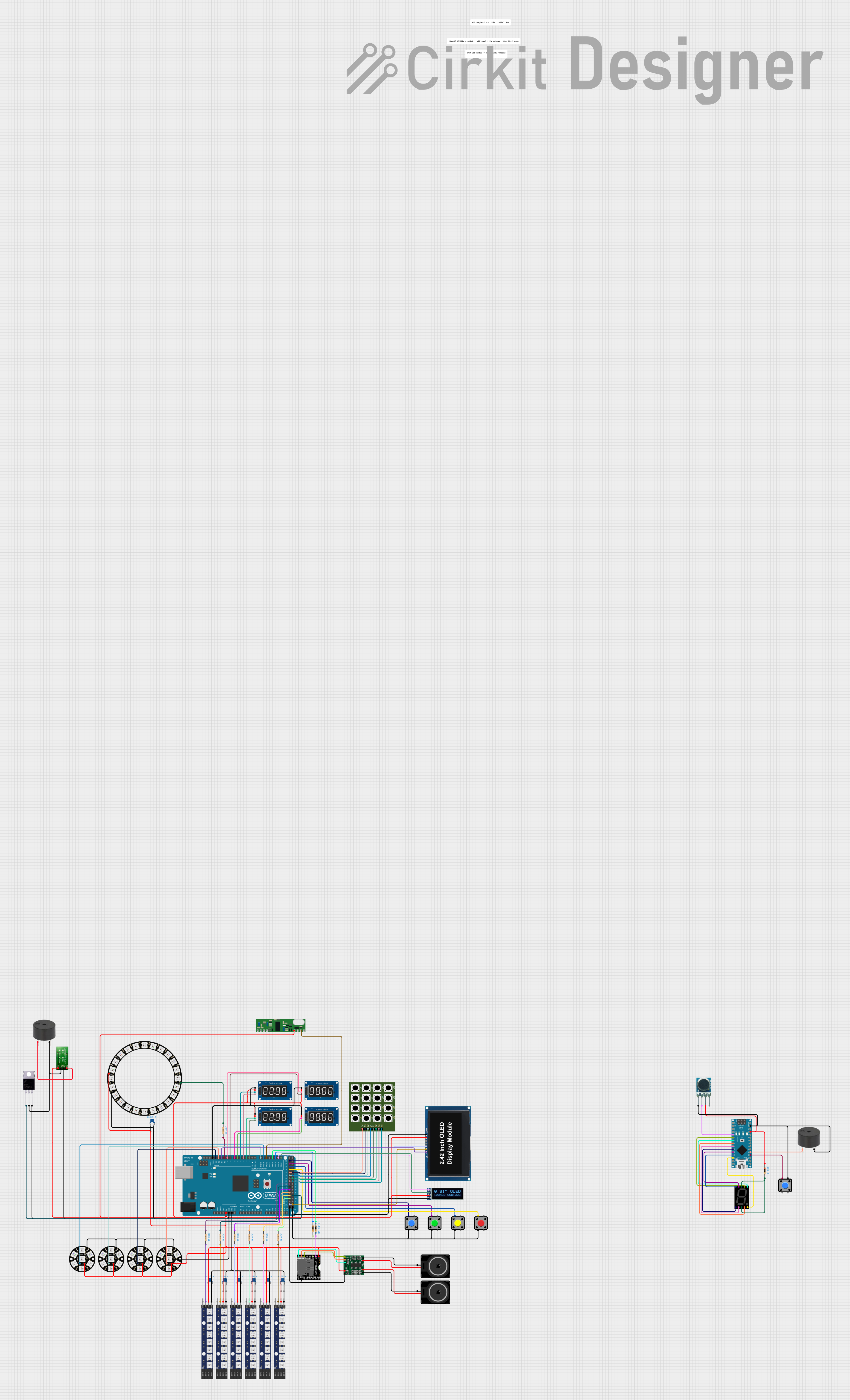
Explore Projects Built with Adafruit FunHouse
Common Applications and Use Cases
- Smart home automation systems
- Environmental monitoring (temperature, humidity, etc.)
- Interactive IoT devices
- Educational projects for learning about sensors and IoT connectivity
- Prototyping IoT solutions for product development
Technical Specifications
Key Technical Details
- Microcontroller: ESP32-S2
- Operating Voltage: 3.3V
- Input Voltage (recommended): 5V via USB-C or battery
- Onboard Sensors:
- Temperature
- Humidity
- PIR motion
- Light
- Barometric pressure
- Display: 1.3" 240x240 TFT capacitive touch
- Connectivity:
- Wi-Fi (802.11b/g/n)
- Bluetooth (BLE)
- GPIO Pins: 10 JST PH connectors for I2C, digital, analog, and PWM
- Additional Features:
- NeoPixel LEDs
- Piezo buzzer
- Mini prototyping area
Pin Configuration and Descriptions
| Pin Number | Function | Description |
|---|---|---|
| 1 | 3V3 | 3.3V power supply |
| 2 | GND | Ground |
| 3 | SDA | I2C data line |
| 4 | SCL | I2C clock line |
| 5-14 | GPIO 0-9 | General-purpose input/output pins |
Usage Instructions
How to Use the Component in a Circuit
Powering the FunHouse:
- Connect a 5V power source to the USB-C port or attach a battery to the JST connector.
Connecting to Wi-Fi:
- Use the ESP32's Wi-Fi capabilities to connect the FunHouse to your local network for IoT applications.
Interacting with Sensors:
- Access the onboard sensors through the ESP32's I2C interface or the provided GPIO pins.
Display and Touch Interface:
- Utilize the capacitive touch display to create interactive interfaces for your projects.
Important Considerations and Best Practices
- Always ensure that the power supply is within the recommended voltage range to prevent damage.
- When connecting external components, verify that they are compatible with the 3.3V logic levels of the ESP32.
- Use proper ESD precautions when handling the FunHouse to avoid damaging the sensitive electronics.
- Regularly update the firmware and libraries to benefit from the latest features and improvements.
Troubleshooting and FAQs
Common Issues Users Might Face
Wi-Fi Connectivity Problems:
- Ensure that the network credentials are correctly entered.
- Check the signal strength and reduce the distance to the router if necessary.
Sensor Readings Are Inaccurate:
- Calibrate the sensors following the manufacturer's guidelines.
- Avoid placing the FunHouse near heat sources or in direct sunlight.
Display or Touch Issues:
- Verify that the display ribbon cable is properly seated.
- Reset the FunHouse if the display is unresponsive.
Solutions and Tips for Troubleshooting
Device Not Powering On:
- Check the power source and cables for any signs of damage.
- Ensure that the battery is charged if using a battery power source.
Code Not Running as Expected:
- Double-check the code for errors and ensure that the correct libraries are included.
- Perform a full erase and re-flash of the firmware if persistent issues occur.
FAQs
Q: Can the FunHouse be powered by batteries?
- A: Yes, it can be powered by an attached LiPo battery.
Q: Is the FunHouse compatible with Arduino IDE?
- A: Yes, with the proper board support package installed, it can be programmed using the Arduino IDE.
Q: How do I update the firmware on the FunHouse?
- A: Firmware updates can be done through the USB-C connection using the provided update tools from Adafruit.
Example Code for Arduino UNO
Below is a simple example code snippet that demonstrates how to blink an onboard LED on the Adafruit FunHouse using the Arduino IDE. This example assumes you have the appropriate board support package installed for the ESP32-S2.
#include <Arduino.h>

// Define the pin for the onboard LED
const int ledPin = 13; // Replace with the correct pin number for the FunHouse

void setup() {
  // Initialize the LED pin as an output
  pinMode(ledPin, OUTPUT);
}

void loop() {
  // Turn the LED on
  digitalWrite(ledPin, HIGH);
  // Wait for one second
  delay(1000);
  // Turn the LED off
  digitalWrite(ledPin, LOW);
  // Wait for one second
  delay(1000);
}
Remember to replace ledPin with the correct pin number for the onboard LED on the Adafruit FunHouse. The above code will toggle the LED on and off every second, creating a blinking effect.