How to Use sensor tegangan: Examples, Pinouts, and Specs
Introduction
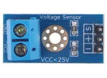
The Sensor Tegangan by ESP32 is a voltage sensor designed to detect and measure voltage levels in a circuit. It provides an output signal proportional to the input voltage, making it ideal for monitoring or control applications. This sensor is commonly used in systems requiring voltage measurement, such as battery monitoring, power supply diagnostics, and energy management systems.
Explore Projects Built with sensor tegangan
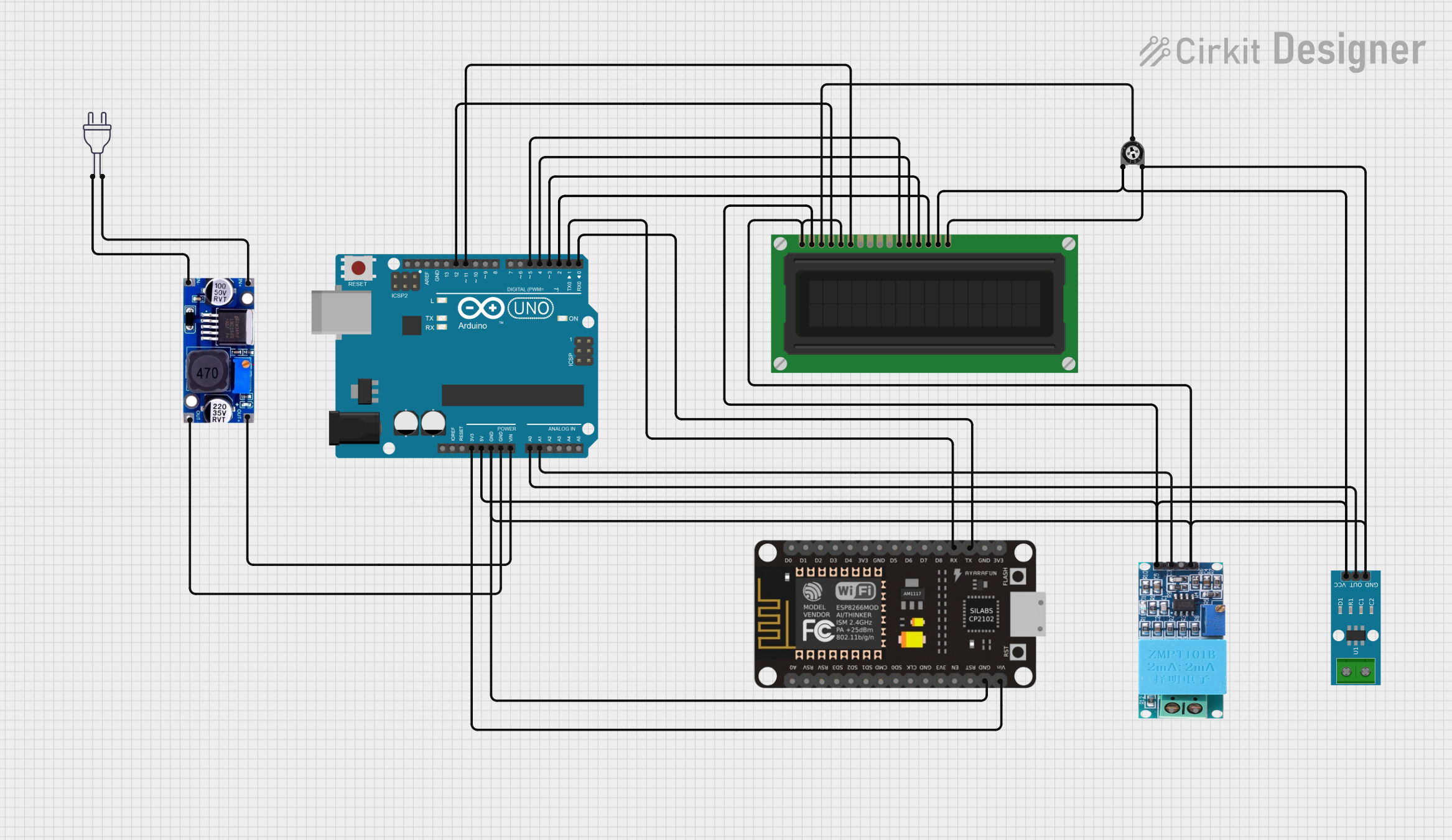

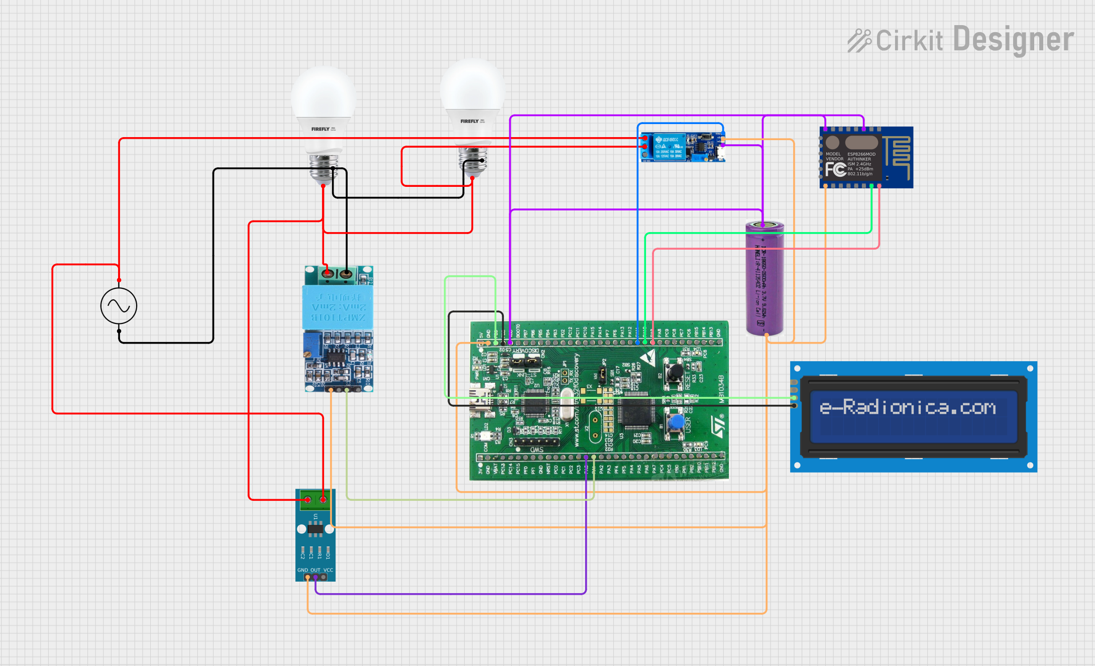
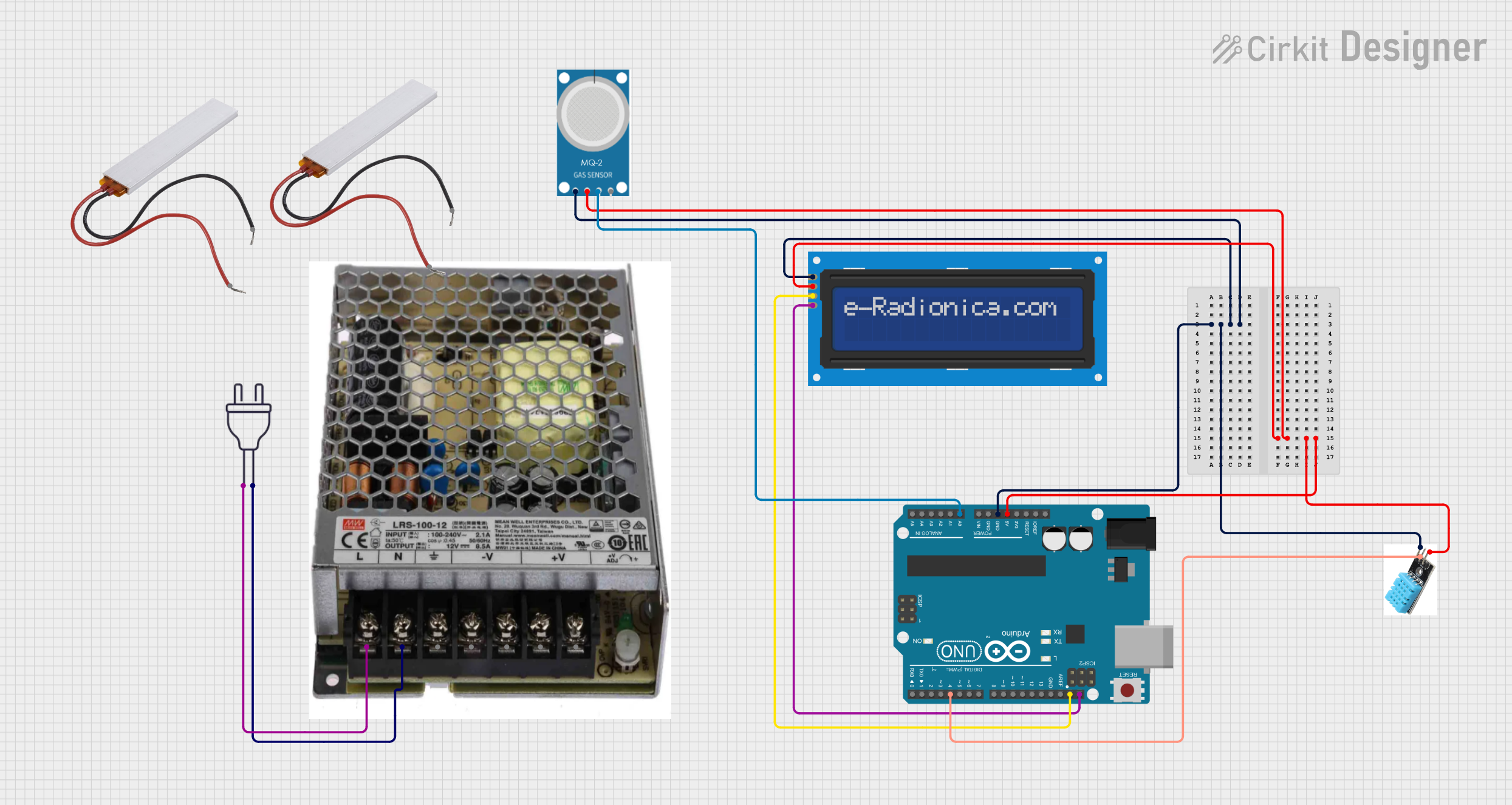
Explore Projects Built with sensor tegangan
Common Applications
- Battery voltage monitoring in IoT devices
- Power supply diagnostics in embedded systems
- Energy management in renewable energy systems
- Voltage measurement in automation and control systems
Technical Specifications
The Sensor Tegangan is designed to work seamlessly with microcontrollers like the ESP32 and Arduino. Below are its key technical details:
Key Specifications
| Parameter | Value |
|---|---|
| Input Voltage Range | 0V to 25V |
| Output Voltage Range | 0V to 3.3V (ESP32 compatible) |
| Voltage Divider Ratio | 5:1 |
| Accuracy | ±1% |
| Operating Temperature | -40°C to 85°C |
| Dimensions | 30mm x 20mm x 10mm |
Pin Configuration
The Sensor Tegangan has a simple pinout for easy integration into circuits. Below is the pin configuration:
| Pin Name | Description |
|---|---|
| VCC | Power supply input (3.3V or 5V) |
| GND | Ground connection |
| OUT | Analog output signal proportional to voltage |
Usage Instructions
How to Use the Sensor Tegangan in a Circuit
- Connect Power Supply:
- Connect the
VCCpin to a 3.3V or 5V power source, depending on your microcontroller. - Connect the
GNDpin to the ground of your circuit.
- Connect the
- Connect the Output:
- Connect the
OUTpin to an analog input pin on your microcontroller (e.g., A0 on Arduino or GPIO36 on ESP32).
- Connect the
- Voltage Measurement:
- The sensor uses a voltage divider to scale down the input voltage. The output voltage is proportional to the input voltage, with a 5:1 ratio. For example, an input voltage of 25V will produce an output of 5V.
Important Considerations
- Input Voltage Limit: Do not exceed the maximum input voltage of 25V to avoid damaging the sensor.
- Output Voltage Range: Ensure the microcontroller's analog input pin can handle the sensor's output range (0V to 3.3V for ESP32).
- Calibration: For accurate measurements, calibrate the sensor by comparing its output with a known reference voltage.
Example Code for ESP32
Below is an example of how to use the Sensor Tegangan with an ESP32 to measure voltage:
// Include necessary libraries
// No additional libraries are required for basic analog reading

// Define the analog pin connected to the sensor
const int sensorPin = 36; // GPIO36 (VP) on ESP32

// Define the voltage divider ratio
const float voltageDividerRatio = 5.0;

// Define the reference voltage of the ESP32 ADC
const float referenceVoltage = 3.3;

void setup() {
  // Initialize serial communication for debugging
  Serial.begin(115200);
}

void loop() {
  // Read the analog value from the sensor
  int analogValue = analogRead(sensorPin);

  // Convert the analog value to a voltage
  float sensorVoltage = (analogValue / 4095.0) * referenceVoltage;

  // Calculate the input voltage using the voltage divider ratio
  float inputVoltage = sensorVoltage * voltageDividerRatio;

  // Print the measured voltage to the Serial Monitor
  Serial.print("Input Voltage: ");
  Serial.print(inputVoltage);
  Serial.println(" V");

  // Wait for 1 second before the next reading
  delay(1000);
}
Notes:
- The ESP32 ADC has a 12-bit resolution, meaning the analogRead() function returns values between 0 and 4095.
- Adjust the
voltageDividerRatioif using a custom voltage divider circuit.
Troubleshooting and FAQs
Common Issues
Incorrect Voltage Readings:
- Cause: The sensor is not calibrated or the voltage divider ratio is incorrect.
- Solution: Verify the voltage divider ratio and calibrate the sensor using a multimeter.
No Output Signal:
- Cause: Improper wiring or insufficient power supply.
- Solution: Check all connections and ensure the sensor is powered correctly.
ESP32 ADC Saturation:
- Cause: Input voltage exceeds the ADC's maximum range (3.3V).
- Solution: Ensure the input voltage to the sensor does not exceed 25V, and the output voltage does not exceed 3.3V.
FAQs
Q: Can I use this sensor with a 5V microcontroller like Arduino UNO?
A: Yes, the sensor is compatible with 5V systems. However, ensure the output voltage does not exceed the ADC input range of your microcontroller.
Q: How do I improve measurement accuracy?
A: Use a stable power supply, calibrate the sensor, and average multiple readings to reduce noise.
Q: What happens if the input voltage exceeds 25V?
A: Exceeding 25V can damage the sensor. Use a higher-rated voltage divider if higher input voltages need to be measured.
By following this documentation, you can effectively integrate the Sensor Tegangan into your projects for accurate voltage measurement and monitoring.