How to Use Bridge Rectifier: Examples, Pinouts, and Specs
Introduction
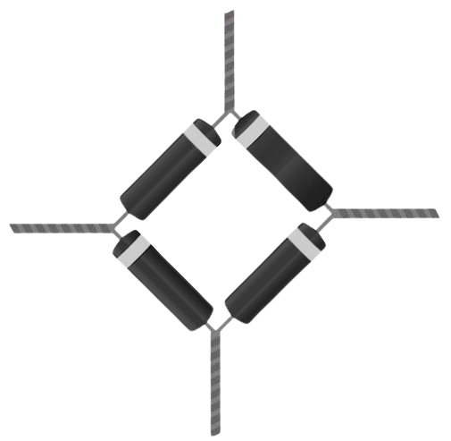
A bridge rectifier is an electrical circuit designed to convert alternating current (AC) into direct current (DC). It achieves this by using four diodes arranged in a bridge configuration. This arrangement allows current to flow in both directions during the AC cycle, enabling full-wave rectification. Bridge rectifiers are widely used in power supplies, battery charging circuits, and other applications where a steady DC voltage is required.
Explore Projects Built with Bridge Rectifier
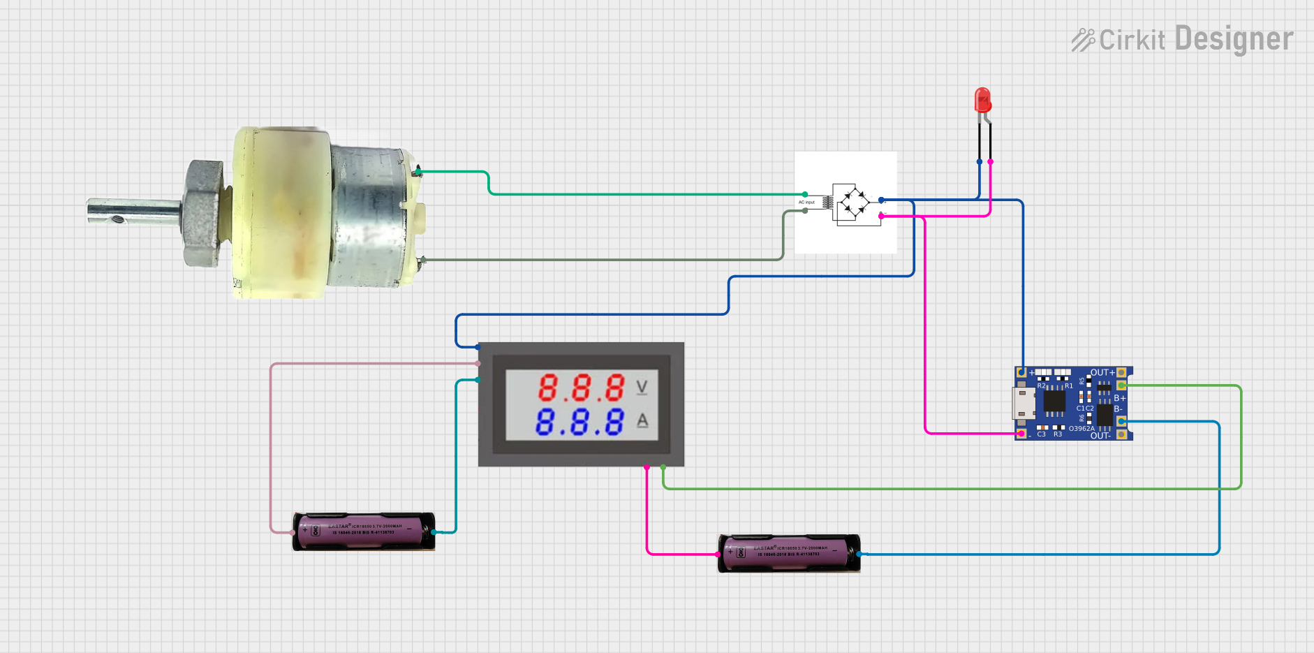
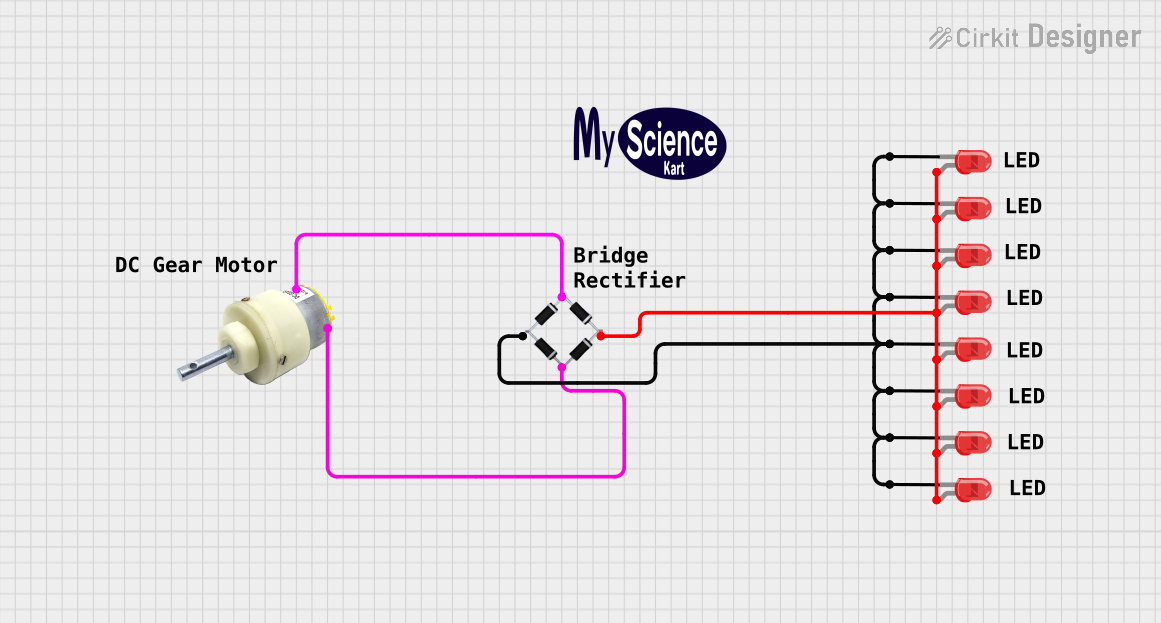
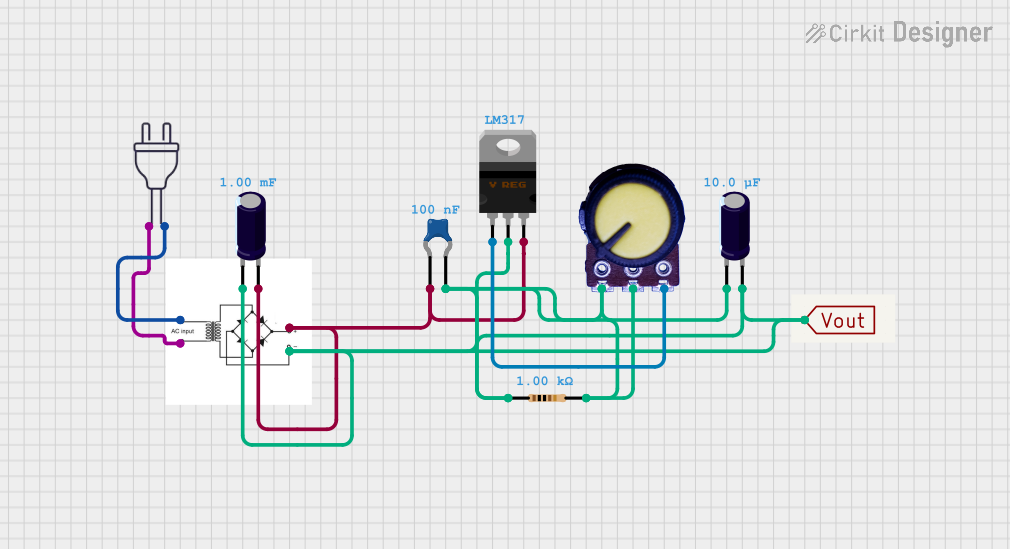
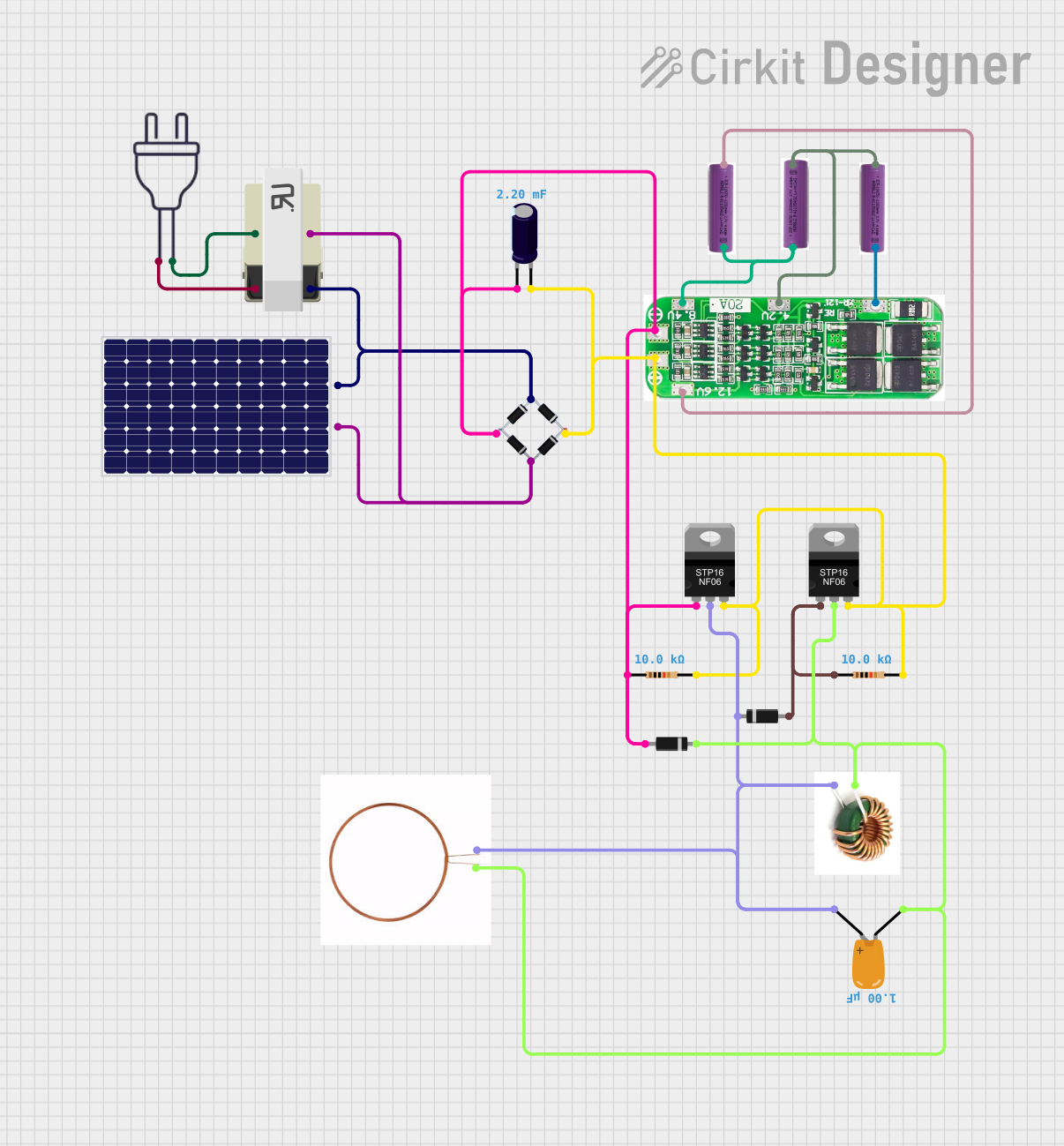
Explore Projects Built with Bridge Rectifier
Common Applications and Use Cases
- Power supply circuits for electronic devices
- Battery charging systems
- DC motor drives
- LED lighting systems
- Rectification in renewable energy systems (e.g., solar panels, wind turbines)
Technical Specifications
Below are the general technical specifications for a standard bridge rectifier. Note that specific values may vary depending on the model and manufacturer.
| Parameter | Typical Value |
|---|---|
| Input Voltage (AC) | 50V to 1000V (depending on model) |
| Output Voltage (DC) | Approximately 0.9 × Input AC Voltage |
| Maximum Current Rating | 1A to 50A (depending on model) |
| Forward Voltage Drop | ~0.7V per diode (1.4V total) |
| Efficiency | ~80% to 90% |
| Operating Temperature | -55°C to +150°C |
Pin Configuration and Descriptions
The bridge rectifier typically has four pins or terminals, as shown in the table below:
| Pin Name | Description |
|---|---|
| AC Input 1 | First AC input terminal (Phase or Neutral) |
| AC Input 2 | Second AC input terminal (Neutral or Phase) |
| DC Output + | Positive DC output terminal |
| DC Output - | Negative DC output terminal |
Usage Instructions
How to Use the Bridge Rectifier in a Circuit
- Connect the AC Input Terminals:
- Attach the two AC input terminals of the bridge rectifier to the AC voltage source. These terminals are typically labeled as "~" or "AC".
- Connect the DC Output Terminals:
- Connect the positive DC output terminal to the positive side of the load.
- Connect the negative DC output terminal to the negative side of the load.
- Add a Filter Capacitor (Optional):
- To smooth the rectified DC output, connect a capacitor across the DC output terminals. The capacitor value depends on the load and desired ripple voltage.
- Verify Connections:
- Double-check all connections to ensure proper polarity and avoid short circuits.
Important Considerations and Best Practices
- Heat Dissipation: Bridge rectifiers can generate heat during operation. Use a heat sink or ensure proper ventilation for high-current applications.
- Voltage Ratings: Ensure the input AC voltage and output DC voltage are within the rectifier's specified range.
- Current Ratings: Do not exceed the maximum current rating of the rectifier to avoid damage.
- Polarity: Always observe the correct polarity when connecting the DC output terminals to the load.
Example: Using a Bridge Rectifier with an Arduino UNO
To power an Arduino UNO using a bridge rectifier, follow these steps:
- Connect the AC input terminals of the bridge rectifier to an AC power source (e.g., a transformer output).
- Connect the positive DC output terminal to the VIN pin of the Arduino UNO.
- Connect the negative DC output terminal to the GND pin of the Arduino UNO.
- Add a filter capacitor (e.g., 1000µF, 25V) across the DC output terminals to smooth the voltage.
Sample Code for Arduino UNO
The following code demonstrates how to read the DC voltage from the bridge rectifier using the Arduino's analog input pin:
// Define the analog input pin
const int voltagePin = A0; // Connect this pin to the DC output of the rectifier

void setup() {
  Serial.begin(9600); // Initialize serial communication at 9600 baud
}

void loop() {
  int sensorValue = analogRead(voltagePin); // Read the analog voltage
  float voltage = sensorValue * (5.0 / 1023.0); // Convert to actual voltage
  Serial.print("Rectified Voltage: ");
  Serial.print(voltage);
  Serial.println(" V");
  delay(1000); // Wait for 1 second before the next reading
}
Troubleshooting and FAQs
Common Issues and Solutions
No Output Voltage:
- Cause: Incorrect wiring or damaged diodes.
- Solution: Verify the connections and check the diodes for continuity using a multimeter.
Excessive Heat:
- Cause: Overloading the rectifier or insufficient heat dissipation.
- Solution: Ensure the load current is within the rectifier's rating and use a heat sink if necessary.
High Ripple Voltage:
- Cause: Insufficient filtering.
- Solution: Add or increase the value of the filter capacitor across the DC output terminals.
Voltage Drop Across the Rectifier:
- Cause: Forward voltage drop of the diodes.
- Solution: This is inherent to the design. Use Schottky diodes for lower voltage drop if necessary.
FAQs
Q1: Can I use a bridge rectifier with a DC input?
A1: No, a bridge rectifier is designed for AC input. Applying DC input may damage the diodes.
Q2: What type of capacitor should I use for filtering?
A2: Use an electrolytic capacitor with a voltage rating at least 1.5 times the output DC voltage.
Q3: Can I use a bridge rectifier for high-frequency AC signals?
A3: Standard bridge rectifiers are not suitable for high-frequency signals. Use fast recovery or Schottky diodes for such applications.