How to Use PWM Vibration Motor Sensor Module Switch: Examples, Pinouts, and Specs
Introduction
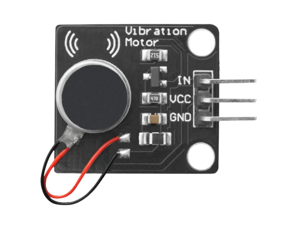
The PWM Vibration Motor Sensor Module Switch is an electronic component designed to provide haptic feedback in the form of vibrations. It is commonly used in devices where a physical response is needed to alert or provide tactile feedback to the user, such as in mobile phones, gaming controllers, and wearables.
Explore Projects Built with PWM Vibration Motor Sensor Module Switch
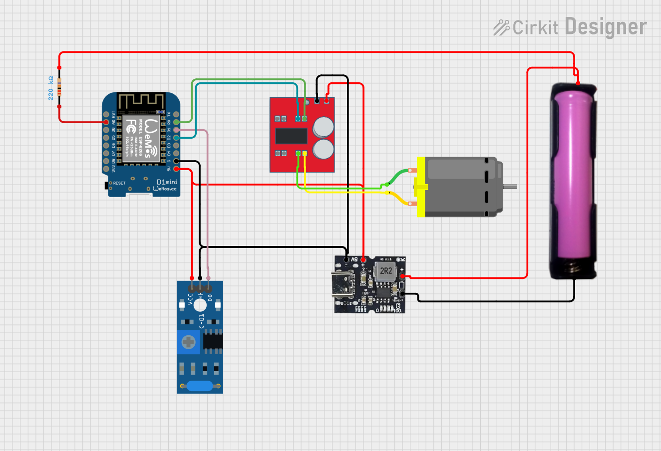
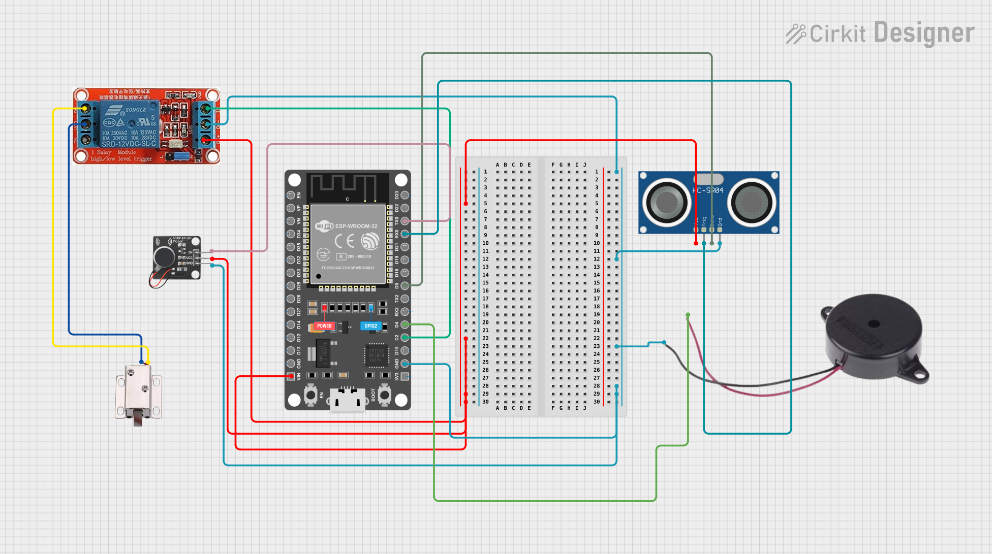
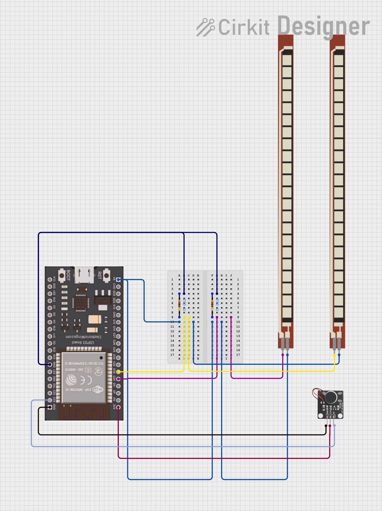
Explore Projects Built with PWM Vibration Motor Sensor Module Switch
Common Applications and Use Cases
- User interface feedback
- Alarms and notifications
- Haptic feedback for touch screens and buttons
- Robotics and automation for sensory feedback
Technical Specifications
Key Technical Details
- Operating Voltage: 3.3V to 5V
- Control Input: PWM (Pulse Width Modulation)
- Vibration Strength: Proportional to PWM signal
- Current Consumption: Depends on the vibration intensity and frequency
Pin Configuration and Descriptions
| Pin Number | Pin Name | Description |
|---|---|---|
| 1 | VCC | Connect to 3.3V or 5V power supply |
| 2 | GND | Connect to ground |
| 3 | SIG | PWM signal input to control vibration |
Usage Instructions
How to Use the Component in a Circuit
- Connect the VCC pin to a 3.3V or 5V power supply from your Arduino Uno.
- Connect the GND pin to one of the GND pins on the Arduino Uno.
- Connect the SIG pin to a PWM-capable digital pin on the Arduino Uno (e.g., D3, D5, D6, D9, D10, or D11).
Important Considerations and Best Practices
- Ensure that the power supply voltage matches the module's requirements.
- Use a PWM signal to control the intensity of the vibration.
- Avoid continuous operation at high vibration levels to prevent overheating and potential damage to the motor.
Example Arduino Code
// Define the PWM pin connected to the SIG pin of the module
const int pwmPin = 9;

void setup() {
  // Set the PWM pin as an output
  pinMode(pwmPin, OUTPUT);
}

void loop() {
  // Increase vibration intensity gradually
  for (int i = 0; i <= 255; i++) {
    analogWrite(pwmPin, i);
    delay(10);
  }
  // Decrease vibration intensity gradually
  for (int i = 255; i >= 0; i--) {
    analogWrite(pwmPin, i);
    delay(10);
  }
}
This example code gradually increases and decreases the intensity of the vibration motor by varying the PWM signal.
Troubleshooting and FAQs
Common Issues Users Might Face
- Motor not vibrating: Check connections and ensure the PWM signal is being sent.
- Weak vibrations: Ensure the power supply is adequate and the PWM signal is within the correct range.
- Motor overheating: Reduce the duty cycle of the PWM signal or allow intervals of rest.
Solutions and Tips for Troubleshooting
- Double-check wiring, especially the VCC and GND connections.
- Use a multimeter to verify the PWM signal from the Arduino Uno.
- Implement a "soft start" by gradually increasing the PWM value to avoid sudden high current draw.
FAQs
Q: Can I use a digital pin that is not PWM-capable to control the motor? A: No, you need to use a PWM-capable pin to control the intensity of the vibrations.
Q: What is the maximum PWM frequency that can be used? A: The maximum PWM frequency depends on the specific motor and the Arduino's capabilities. Typically, a frequency around 1 kHz is a good starting point.
Q: How do I change the pattern of vibration? A: You can change the pattern by adjusting the PWM signal in your code to create different vibration effects.
Q: Is it possible to control multiple vibration motors with one Arduino Uno? A: Yes, as long as you have enough PWM-capable pins and your power supply can handle the current draw of multiple motors.