How to Use 100:1 Metal Gearmotor 37Dx73L mm 24V with 64 CPR Encoder (Helical Pinion): Examples, Pinouts, and Specs
Introduction
The 100:1 Metal Gearmotor 37Dx73L mm 24V with 64 CPR Encoder, manufactured by Pololu (Part ID: 4695), is a compact and efficient gearmotor designed for high-torque applications. It features a 100:1 gear ratio, operates at 24V, and includes a built-in quadrature encoder with 64 counts per revolution (CPR) for precise position and speed feedback. The helical pinion design ensures smoother operation and reduced noise compared to traditional straight-cut gears.
Explore Projects Built with 100:1 Metal Gearmotor 37Dx73L mm 24V with 64 CPR Encoder (Helical Pinion)

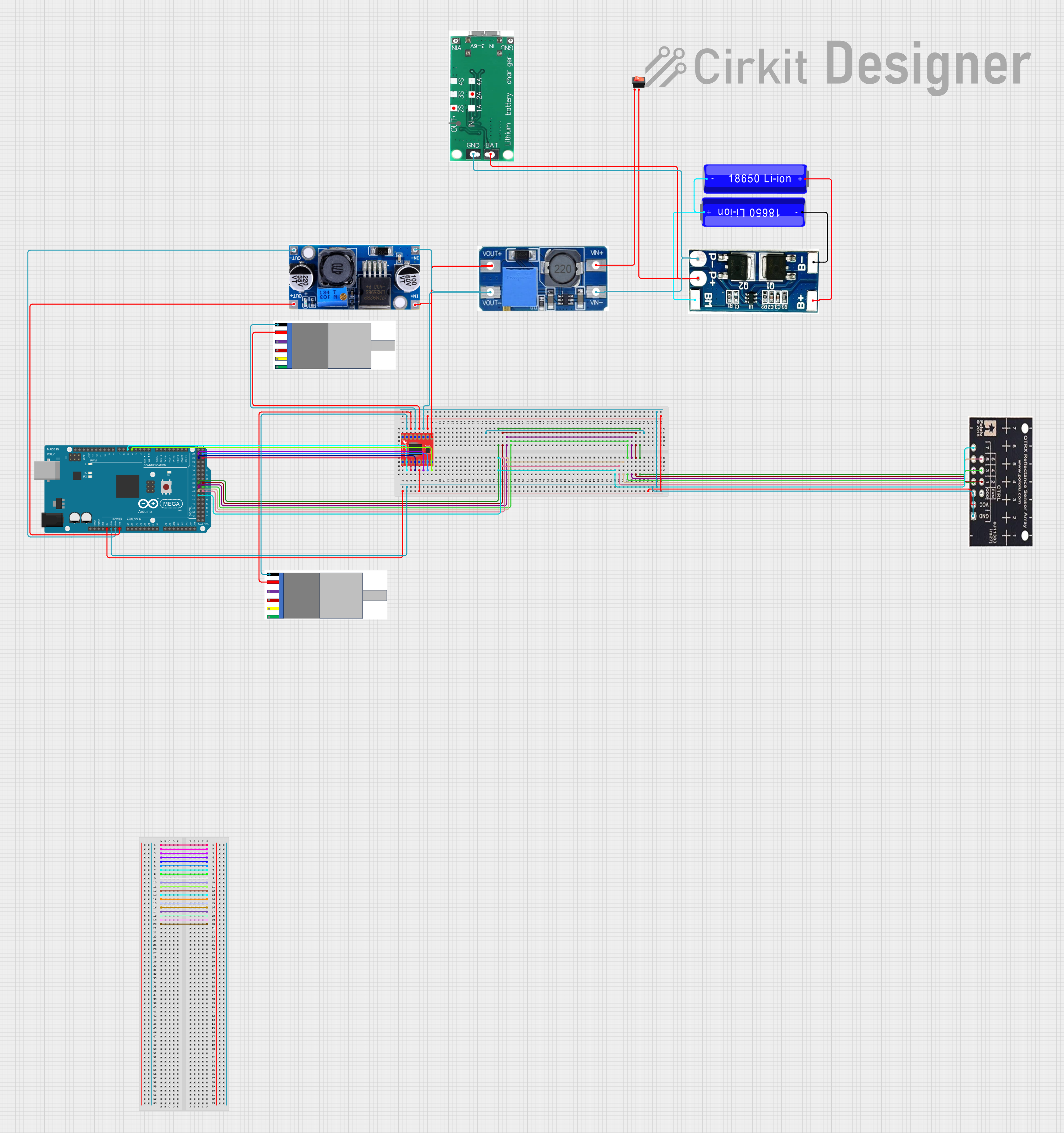
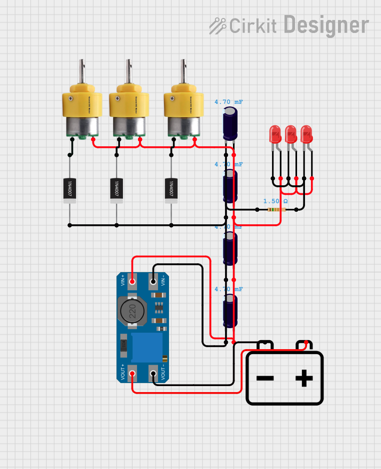
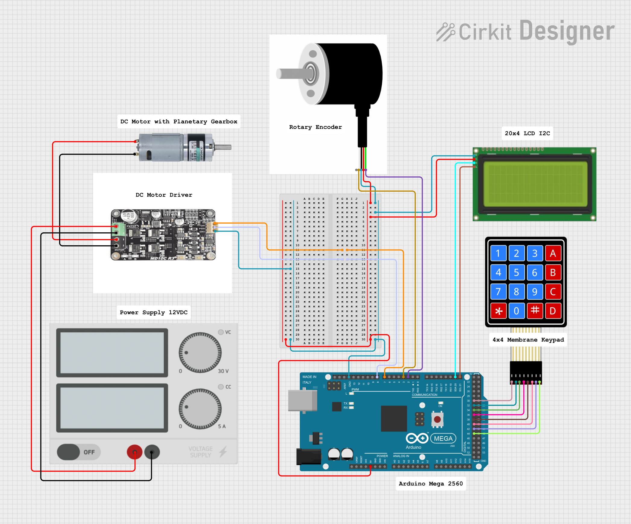
Explore Projects Built with 100:1 Metal Gearmotor 37Dx73L mm 24V with 64 CPR Encoder (Helical Pinion)
Common Applications
- Robotics (e.g., mobile robots, robotic arms)
- Automated systems (e.g., conveyor belts, actuators)
- Precision motion control
- Industrial machinery
- Hobbyist and DIY projects requiring high torque and precise feedback
Technical Specifications
Key Specifications
| Parameter | Value |
|---|---|
| Gear Ratio | 100:1 |
| Operating Voltage | 24V |
| No-Load Speed | ~100 RPM |
| Stall Torque | ~11 kg·cm (at 24V) |
| Stall Current | ~5.5 A (at 24V) |
| Encoder Type | Quadrature Encoder |
| Encoder Resolution | 64 CPR (counts per revolution) |
| Shaft Diameter | 6 mm |
| Motor Dimensions | 37 mm diameter, 73 mm length |
| Weight | ~300 g |
Pin Configuration and Descriptions
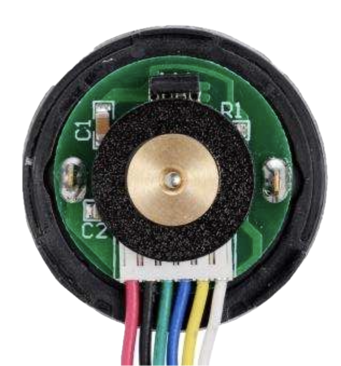
The motor has two main terminals for power and four additional pins for the encoder. The pinout is as follows:
Motor Power Terminals
| Terminal | Description |
|---|---|
| M+ | Motor positive lead |
| M- | Motor negative lead |
Encoder Pinout
| Pin | Wire Color | Description |
|---|---|---|
| VCC | Red | Encoder power supply (3.5V–20V) |
| GND | Black | Ground |
| A | Yellow | Encoder channel A output |
| B | White | Encoder channel B output |
Note: The encoder outputs are open-drain and require pull-up resistors for proper operation.
Usage Instructions
How to Use the Component in a Circuit
Powering the Motor:
- Connect the motor terminals (M+ and M-) to a motor driver capable of handling the motor's voltage (24V) and current (up to 5.5A).
- Use a motor driver with PWM control for speed regulation.
Connecting the Encoder:
- Supply power to the encoder by connecting the VCC pin to a voltage source (3.5V–20V) and the GND pin to ground.
- Connect the A and B pins to microcontroller GPIO pins configured as digital inputs.
- Add pull-up resistors (e.g., 10 kΩ) to the A and B lines if not already provided by the microcontroller.
Controlling the Motor:
- Use a motor driver or H-bridge to control the motor's direction and speed.
- For precise position or speed control, read the encoder signals (A and B) to determine the motor's rotation and direction.
Important Considerations and Best Practices
- Power Supply: Ensure the power supply can provide sufficient current (up to 5.5A) to avoid voltage drops or motor stalling.
- Heat Dissipation: Prolonged operation at high loads may cause the motor to heat up. Allow adequate ventilation or use a heat sink if necessary.
- Encoder Signal Noise: Use shielded cables for the encoder connections to minimize noise interference.
- Mounting: Secure the motor using the mounting holes to prevent vibration or misalignment during operation.
Example: Using with Arduino UNO
Below is an example of how to read the encoder signals using an Arduino UNO:
// Define encoder pins
const int encoderPinA = 2; // Channel A connected to digital pin 2
const int encoderPinB = 3; // Channel B connected to digital pin 3

volatile int encoderCount = 0; // Variable to store encoder count
int lastEncoded = 0;           // Tracks the last encoder state

void setup() {
  pinMode(encoderPinA, INPUT_PULLUP); // Enable pull-up resistor on pin A
  pinMode(encoderPinB, INPUT_PULLUP); // Enable pull-up resistor on pin B

  // Attach interrupts to encoder pins
  attachInterrupt(digitalPinToInterrupt(encoderPinA), updateEncoder, CHANGE);
  attachInterrupt(digitalPinToInterrupt(encoderPinB), updateEncoder, CHANGE);

  Serial.begin(9600); // Initialize serial communication
}

void loop() {
  // Print the encoder count to the serial monitor
  Serial.print("Encoder Count: ");
  Serial.println(encoderCount);
  delay(100); // Delay for readability
}

void updateEncoder() {
  // Read the current state of the encoder pins
  int MSB = digitalRead(encoderPinA); // Most significant bit
  int LSB = digitalRead(encoderPinB); // Least significant bit

  int encoded = (MSB << 1) | LSB; // Combine the two bits
  int sum = (lastEncoded << 2) | encoded; // Track state changes

  // Update encoder count based on state transitions
  if (sum == 0b1101 || sum == 0b0100 || sum == 0b0010 || sum == 0b1011) encoderCount++;
  if (sum == 0b1110 || sum == 0b0111 || sum == 0b0001 || sum == 0b1000) encoderCount--;

  lastEncoded = encoded; // Update the last state
}
Note: This code assumes the encoder outputs are connected to pins 2 and 3 on the Arduino UNO. Adjust the pin numbers as needed for your setup.
Troubleshooting and FAQs
Common Issues and Solutions
Motor Does Not Spin:
- Cause: Insufficient power supply or incorrect wiring.
- Solution: Verify the power supply voltage and current. Check the motor driver connections.
Encoder Signals Are Unstable:
- Cause: Electrical noise or missing pull-up resistors.
- Solution: Use shielded cables for the encoder and add pull-up resistors to the A and B lines.
Motor Overheats:
- Cause: Prolonged operation at high loads or insufficient ventilation.
- Solution: Reduce the load or provide better cooling.
Incorrect Encoder Readings:
- Cause: Misaligned wiring or incorrect interrupt configuration.
- Solution: Double-check the encoder pin connections and ensure the microcontroller is configured correctly.
FAQs
Q: Can I use this motor with a 12V power supply?
- A: While the motor is designed for 24V, it can operate at lower voltages with reduced performance (e.g., lower speed and torque).
Q: What is the maximum RPM of this motor?
- A: The no-load speed is approximately 100 RPM at 24V.
Q: Do I need external pull-up resistors for the encoder?
- A: Yes, the encoder outputs are open-drain and require pull-up resistors for proper operation.
Q: Can I use this motor for continuous operation?
- A: Yes, but ensure proper cooling and avoid exceeding the motor's rated load to prevent overheating.