How to Use BTA12 to-220: Examples, Pinouts, and Specs
Introduction
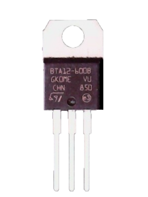
The BTA12 is a triac (triode for alternating current) manufactured by STMicroelectronics. It is designed for controlling AC loads in a variety of applications. The BTA12 is capable of switching and controlling high-power AC signals, making it ideal for use in motor control, lighting dimmers, heating systems, and other industrial or consumer electronics. Its TO-220 package ensures efficient heat dissipation, allowing it to handle significant power levels while maintaining reliability.
Explore Projects Built with BTA12 to-220
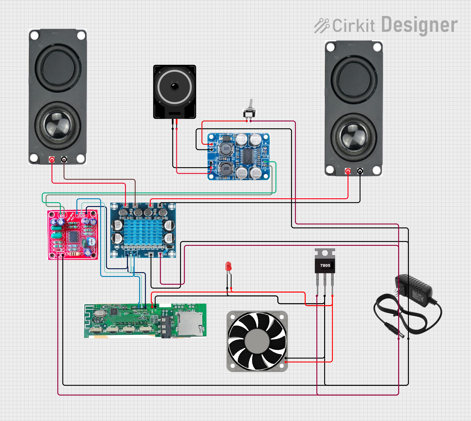
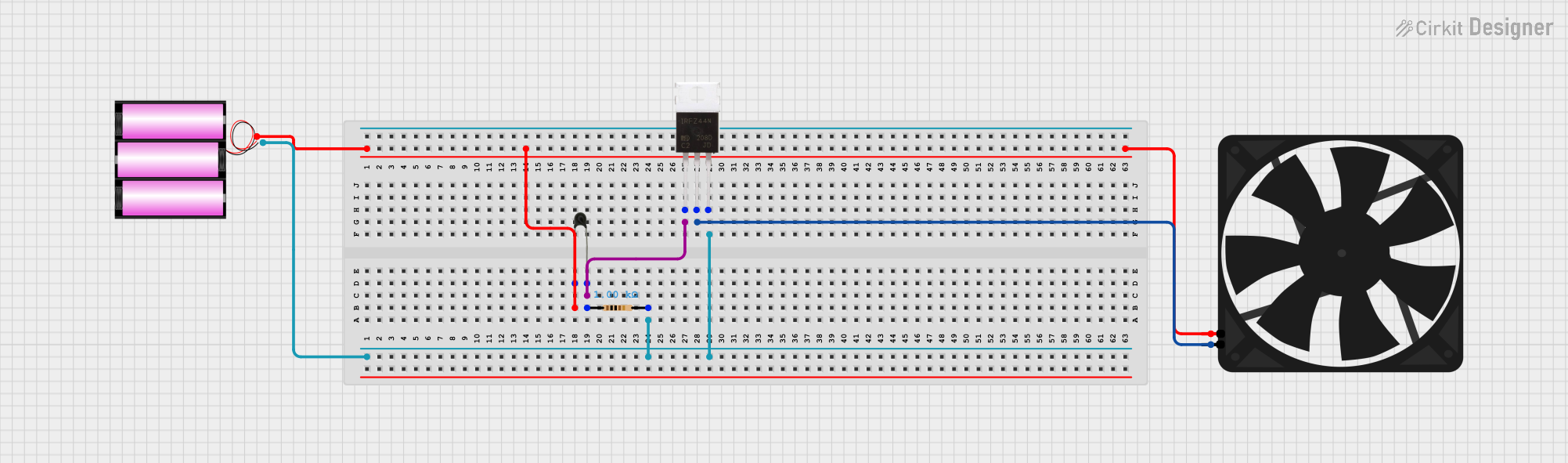


Explore Projects Built with BTA12 to-220
Common Applications
- AC motor speed control
- Light dimming circuits
- Heating element control
- Industrial automation systems
- Home appliances (e.g., fans, ovens, and washing machines)
Technical Specifications
The BTA12 is a robust and versatile triac with the following key specifications:
| Parameter | Value |
|---|---|
| Maximum Repetitive Voltage (VDRM, VRRM) | 600V / 800V (depending on variant) |
| Maximum RMS On-State Current (IT(RMS)) | 12A |
| Peak Non-Repetitive Surge Current (ITSM) | 120A (10ms half-sine wave) |
| Gate Trigger Current (IGT) | 35mA (typical) |
| Holding Current (IH) | 25mA (typical) |
| Operating Temperature Range | -40°C to +125°C |
| Package Type | TO-220 |
Pin Configuration
The BTA12 features three pins, as described in the table below:
| Pin Number | Pin Name | Description |
|---|---|---|
| 1 | MT1 (Main Terminal 1) | Connected to one side of the AC load. |
| 2 | MT2 (Main Terminal 2) | Connected to the other side of the AC load. |
| 3 | Gate (G) | Used to trigger the triac into conduction mode. |
Usage Instructions
The BTA12 is commonly used in circuits to control AC loads. Below are the steps and considerations for using the component effectively:
Basic Circuit Design
- Connect the Load: Attach the AC load between MT2 and the AC power source.
- Gate Triggering: Use a resistor to limit the current to the Gate pin. A small DC voltage or pulse is applied to the Gate to trigger the triac.
- Snubber Circuit: For inductive loads (e.g., motors), include a snubber circuit (a resistor and capacitor in series) across MT1 and MT2 to prevent voltage spikes.
- Heat Dissipation: Mount the BTA12 on a heatsink to ensure proper thermal management, especially for high-power applications.
Example Circuit with Arduino UNO
The BTA12 can be controlled using an Arduino UNO to switch an AC load. Below is an example:
Circuit Connections
- MT1: Connect to the neutral line of the AC power source.
- MT2: Connect to one terminal of the AC load. The other terminal of the load connects to the live line of the AC power source.
- Gate: Connect to a 220-ohm resistor, which is then connected to an Arduino digital output pin (e.g., D3).
- Snubber Circuit: Place a 100Ω resistor and 0.01µF capacitor in series across MT1 and MT2.
Arduino Code
// Example code to control the BTA12 triac with an Arduino UNO
// This code turns an AC load ON and OFF with a 1-second delay.

const int triacGatePin = 3; // Pin connected to the Gate of the BTA12

void setup() {
  pinMode(triacGatePin, OUTPUT); // Set the Gate pin as an output
}

void loop() {
  digitalWrite(triacGatePin, HIGH); // Trigger the triac to turn ON the load
  delay(1000);                      // Keep the load ON for 1 second
  digitalWrite(triacGatePin, LOW);  // Turn OFF the triac (load will turn OFF)
  delay(1000);                      // Keep the load OFF for 1 second
}
Important Considerations
- Gate Drive: Ensure the gate current is sufficient to trigger the triac. Use a resistor to limit the current to the Gate pin.
- Isolation: For safety, use an optocoupler to isolate the control circuit (e.g., Arduino) from the high-voltage AC circuit.
- Thermal Management: Always use a heatsink to prevent overheating during operation.
- AC Voltage: Ensure the AC voltage does not exceed the maximum repetitive voltage rating of the BTA12.
Troubleshooting and FAQs
Common Issues
Triac Does Not Trigger:
- Check if the gate current is sufficient (minimum 35mA).
- Verify the resistor value used in the gate circuit.
- Ensure the control signal is reaching the Gate pin.
Triac Overheats:
- Ensure a proper heatsink is installed.
- Check if the load current exceeds the maximum RMS current rating (12A).
- Verify the snubber circuit for inductive loads.
Load Flickers or Does Not Turn Off:
- Check for noise or voltage spikes in the AC line.
- Verify the snubber circuit is correctly installed.
- Ensure the holding current (IH) is met for the load.
FAQs
Q: Can the BTA12 be used for DC loads?
A: No, the BTA12 is designed for AC loads. It requires the alternating nature of AC to turn off (commutation).
Q: What is the purpose of the snubber circuit?
A: The snubber circuit prevents voltage spikes caused by inductive loads, which can damage the triac or cause erratic behavior.
Q: How do I calculate the gate resistor value?
A: Use Ohm's law: R = (Vcontrol - VGT) / IGT, where Vcontrol is the control voltage, VGT is the gate trigger voltage, and IGT is the gate trigger current.
By following these guidelines and best practices, the BTA12 can be effectively used in a wide range of AC control applications.