How to Use 5VcoilRelay: Examples, Pinouts, and Specs
Introduction
The 5VcoilRelay (Manufacturer: Finder, Part ID: 32.21.4000) is an electromechanical relay designed to operate with a 5V DC coil voltage. It is commonly used to control high-power devices, such as motors, lights, or heaters, using low-power control signals. This relay acts as an electrically operated switch, enabling isolation between the control circuit and the load circuit.
Explore Projects Built with 5VcoilRelay


Explore Projects Built with 5VcoilRelay
Common Applications and Use Cases
- Home automation systems
- Industrial control panels
- Motor control circuits
- Switching high-power AC or DC loads
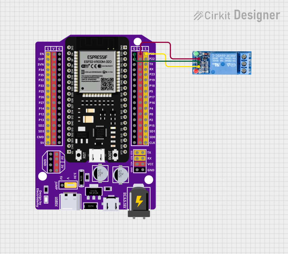
- Microcontroller-based projects (e.g., Arduino, Raspberry Pi)
Technical Specifications
Key Technical Details
| Parameter | Value |
|---|---|
| Manufacturer | Finder |
| Part ID | 32.21.4000 |
| Coil Voltage | 5V DC |
| Coil Resistance | 125 Ω |
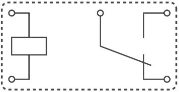
| Contact Configuration | SPDT (Single Pole Double Throw) |
| Contact Rating | 10A at 250V AC / 30V DC |
| Switching Voltage (Max) | 250V AC / 30V DC |
| Switching Current (Max) | 10A |
| Dielectric Strength | 4000V AC (coil to contacts) |
| Operating Temperature | -40°C to +85°C |
| Dimensions | 29mm x 12.7mm x 15.7mm |
Pin Configuration and Descriptions
The 5VcoilRelay has a total of 5 pins. The pinout is as follows:
| Pin Number | Name | Description |
|---|---|---|
| 1 | Coil (+) | Positive terminal of the relay coil (5V DC input). |
| 2 | Coil (-) | Negative terminal of the relay coil (ground). |
| 3 | Common (COM) | Common terminal for the load circuit. |
| 4 | Normally Open (NO) | Open when the relay is inactive; closes when the relay is energized. |
| 5 | Normally Closed (NC) | Closed when the relay is inactive; opens when the relay is energized. |
Usage Instructions
How to Use the Component in a Circuit
- Power the Coil: Connect the coil terminals (Pin 1 and Pin 2) to a 5V DC power source. Ensure the polarity is correct.
- Control the Load:
- Connect the load circuit to the Common (COM) terminal (Pin 3).
- Use the Normally Open (NO) terminal (Pin 4) if you want the load to be powered only when the relay is energized.
- Use the Normally Closed (NC) terminal (Pin 5) if you want the load to be powered when the relay is not energized.
- Isolation: Ensure proper isolation between the control circuit and the load circuit to prevent damage to sensitive components.
Important Considerations and Best Practices
- Flyback Diode: Always connect a flyback diode across the coil terminals to protect the driving circuit from voltage spikes when the relay is de-energized.
- Current Rating: Ensure the load current does not exceed the relay's maximum contact rating (10A).
- Heat Dissipation: If the relay operates frequently, ensure adequate ventilation to prevent overheating.
- Microcontroller Compatibility: Use a transistor or relay driver module to interface the relay with microcontrollers like Arduino, as they cannot directly supply sufficient current to the relay coil.
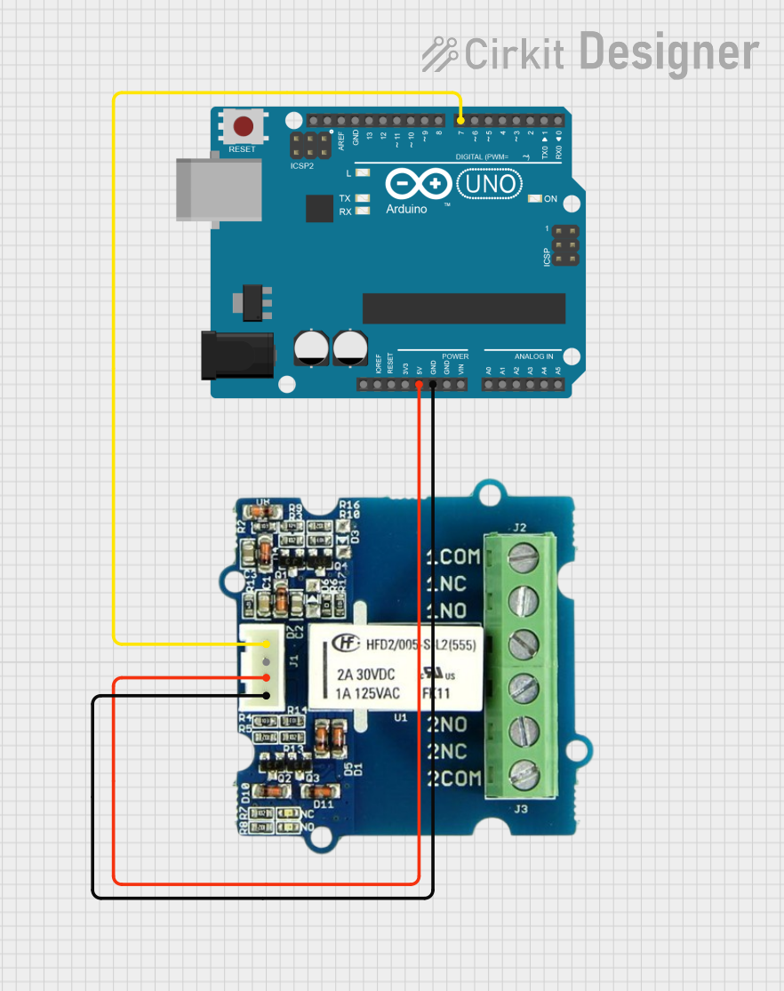
Example: Connecting to an Arduino UNO
Below is an example of how to control the 5VcoilRelay using an Arduino UNO:
Circuit Diagram
- Connect Pin 1 (Coil +) to the collector of an NPN transistor (e.g., 2N2222).
- Connect Pin 2 (Coil -) to the ground (GND).
- Connect the emitter of the transistor to GND.
- Connect a 1kΩ resistor between the Arduino digital pin (e.g., D8) and the base of the transistor.
- Place a flyback diode (e.g., 1N4007) across the coil terminals, with the cathode connected to Pin 1.
Arduino Code
// Define the relay control pin
const int relayPin = 8;

void setup() {
  // Set the relay pin as an output
  pinMode(relayPin, OUTPUT);
}

void loop() {
  // Turn the relay ON
  digitalWrite(relayPin, HIGH);
  delay(1000); // Keep the relay ON for 1 second

  // Turn the relay OFF
  digitalWrite(relayPin, LOW);
  delay(1000); // Keep the relay OFF for 1 second
}
Troubleshooting and FAQs
Common Issues and Solutions
Relay Not Switching:
- Cause: Insufficient voltage or current to the coil.
- Solution: Verify that the coil is receiving 5V DC and sufficient current (40mA).
Load Not Powering On:
- Cause: Incorrect wiring of the load circuit.
- Solution: Double-check the connections to the COM, NO, and NC terminals.
Microcontroller Resetting:
- Cause: Voltage spikes from the relay coil.
- Solution: Ensure a flyback diode is installed across the coil terminals.
Relay Overheating:
- Cause: Exceeding the maximum current rating.
- Solution: Ensure the load current does not exceed 10A.
FAQs
Q: Can I use the 5VcoilRelay with a 3.3V microcontroller?
A: Yes, but you will need a transistor or relay driver circuit to step up the control voltage to 5V.
Q: Is the relay suitable for switching DC loads?
A: Yes, the relay can switch DC loads up to 30V and 10A.
Q: Can I use the relay for high-frequency switching?
A: No, electromechanical relays like the 5VcoilRelay are not suitable for high-frequency switching due to mechanical limitations.
Q: What is the purpose of the flyback diode?
A: The flyback diode protects the driving circuit from voltage spikes generated when the relay coil is de-energized.