Cirkit Designer Logo
Cirkit Designer
Your all-in-one circuit design IDE
Home / 
Component Documentation

How to Use Adafruit VEML6075 UV Sensor Breakout: Examples, Pinouts, and Specs

Image of Adafruit VEML6075 UV Sensor Breakout
Cirkit Designer LogoDesign with Adafruit VEML6075 UV Sensor Breakout in Cirkit Designer

Introduction

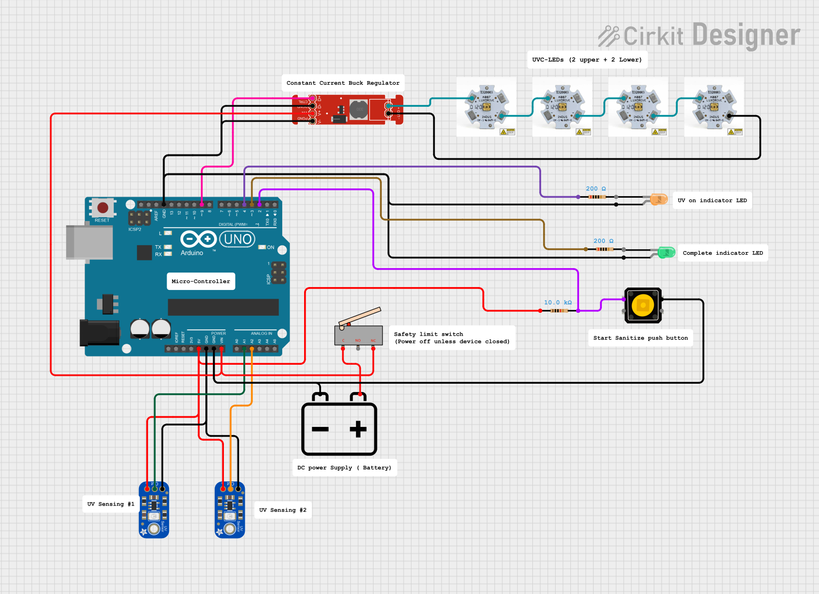
The Adafruit VEML6075 UV Sensor Breakout is a sophisticated sensor module designed to measure the intensity of ultraviolet (UV) light. This sensor is equipped with an integrated UV photodiode and ambient light sensor, which allows it to detect UVA and UVB light with high accuracy. The VEML6075 communicates with microcontrollers such as the Arduino UNO via the I2C interface, making it an excellent choice for a wide range of applications, including UV index monitoring, UV exposure measurement, and UV lamp intensity control.

Explore Projects Built with Adafruit VEML6075 UV Sensor Breakout

Use Cirkit Designer to design, explore, and prototype these projects online. Some projects support real-time simulation. Click "Open Project" to start designing instantly!
ESP32-Based UV Index Sensor with VEML6075
Image of ESP32 VEML6075: A project utilizing Adafruit VEML6075 UV Sensor Breakout in a practical application
This circuit connects an ESP32 Wroom Dev Kit microcontroller with a VEML6075 UV light sensor. The ESP32 powers the sensor and communicates with it via I2C, using GPIO 32 and GPIO 33 for the SCL and SDA lines, respectively. The purpose of this circuit is to enable the ESP32 to read UV index measurements from the VEML6075 sensor.
Cirkit Designer LogoOpen Project in Cirkit Designer
Wi-Fi Enabled UV Monitoring System with OLED Display
Image of UV_DETECTOR_BREADBOARD: A project utilizing Adafruit VEML6075 UV Sensor Breakout in a practical application
This circuit features a PicoW microcontroller interfacing with a 0.96" OLED display, an ML8511 UV sensor, and a blue LED. The PicoW reads UV sensor data and can display information on the OLED while controlling the LED for visual feedback.
Cirkit Designer LogoOpen Project in Cirkit Designer
Raspberry Pi Pico W UV Monitoring System with OLED Display and RTC
Image of PCB_UV_METER: A project utilizing Adafruit VEML6075 UV Sensor Breakout in a practical application
This circuit features a Raspberry Pi Pico W microcontroller interfaced with a 128x64 OLED display, an RTC module, and an ML8511 UV sensor. The microcontroller reads UV sensor data and can display information on the OLED screen while keeping track of time using the RTC module. Power and ground connections are shared among all components.
Cirkit Designer LogoOpen Project in Cirkit Designer
Arduino-Controlled UV LED Sterilization System with Dual UV Sensors
Image of SAN-CATH: A project utilizing Adafruit VEML6075 UV Sensor Breakout in a practical application
This circuit uses an Arduino UNO to control a set of UV-C LEDs via a FemtoBuck LED driver, based on input from two UV light sensors. The UV LEDs are activated by a push button and remain on until the sensors detect a desired UV level, at which point the LEDs are turned off and a green indicator LED is lit.
Cirkit Designer LogoOpen Project in Cirkit Designer

Explore Projects Built with Adafruit VEML6075 UV Sensor Breakout

Use Cirkit Designer to design, explore, and prototype these projects online. Some projects support real-time simulation. Click "Open Project" to start designing instantly!
Image of ESP32 VEML6075: A project utilizing Adafruit VEML6075 UV Sensor Breakout in a practical application
ESP32-Based UV Index Sensor with VEML6075
This circuit connects an ESP32 Wroom Dev Kit microcontroller with a VEML6075 UV light sensor. The ESP32 powers the sensor and communicates with it via I2C, using GPIO 32 and GPIO 33 for the SCL and SDA lines, respectively. The purpose of this circuit is to enable the ESP32 to read UV index measurements from the VEML6075 sensor.
Cirkit Designer LogoOpen Project in Cirkit Designer
Image of UV_DETECTOR_BREADBOARD: A project utilizing Adafruit VEML6075 UV Sensor Breakout in a practical application
Wi-Fi Enabled UV Monitoring System with OLED Display
This circuit features a PicoW microcontroller interfacing with a 0.96" OLED display, an ML8511 UV sensor, and a blue LED. The PicoW reads UV sensor data and can display information on the OLED while controlling the LED for visual feedback.
Cirkit Designer LogoOpen Project in Cirkit Designer
Image of PCB_UV_METER: A project utilizing Adafruit VEML6075 UV Sensor Breakout in a practical application
Raspberry Pi Pico W UV Monitoring System with OLED Display and RTC
This circuit features a Raspberry Pi Pico W microcontroller interfaced with a 128x64 OLED display, an RTC module, and an ML8511 UV sensor. The microcontroller reads UV sensor data and can display information on the OLED screen while keeping track of time using the RTC module. Power and ground connections are shared among all components.
Cirkit Designer LogoOpen Project in Cirkit Designer
Image of SAN-CATH: A project utilizing Adafruit VEML6075 UV Sensor Breakout in a practical application
Arduino-Controlled UV LED Sterilization System with Dual UV Sensors
This circuit uses an Arduino UNO to control a set of UV-C LEDs via a FemtoBuck LED driver, based on input from two UV light sensors. The UV LEDs are activated by a push button and remain on until the sensors detect a desired UV level, at which point the LEDs are turned off and a green indicator LED is lit.
Cirkit Designer LogoOpen Project in Cirkit Designer

Technical Specifications

Key Technical Details

  • UV Wavelength Range: UVA (315-400 nm), UVB (280-315 nm)
  • Interface: I2C (default I2C address: 0x10)
  • Operating Voltage: 3.3V (Do not exceed 3.6V)
  • Current Consumption: Typ. 480 μA
  • Operating Temperature Range: -40°C to +85°C

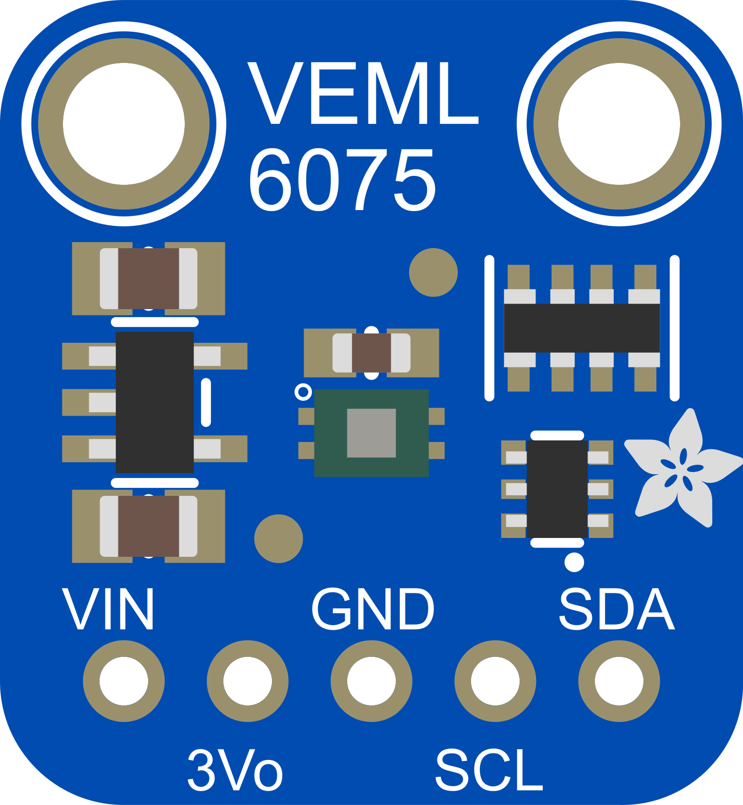
Pin Configuration and Descriptions

Pin Number Pin Name Description
1 VIN Power supply (3.3V input)
2 GND Ground
3 SDA I2C Data line
4 SCL I2C Clock line
5 - No connection (NC)

Usage Instructions

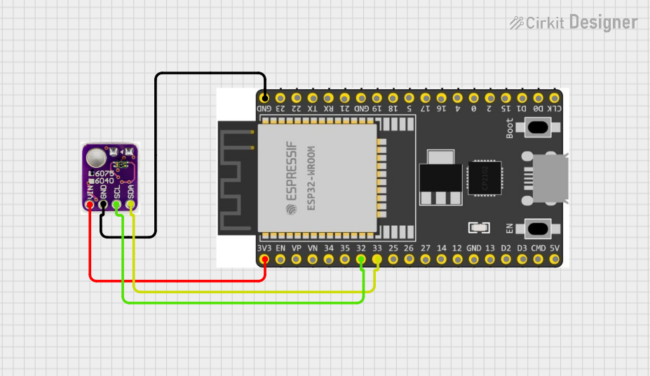
Integration with a Circuit

To use the VEML6075 UV Sensor with a microcontroller like the Arduino UNO, follow these steps:

  1. Connect the VIN pin to the 3.3V output on the Arduino.
  2. Connect the GND pin to one of the GND pins on the Arduino.
  3. Connect the SDA pin to the A4 pin (SDA) on the Arduino UNO.
  4. Connect the SCL pin to the A5 pin (SCL) on the Arduino UNO.

Best Practices

  • Ensure that the power supply does not exceed 3.6V to prevent damage to the sensor.
  • Use pull-up resistors on the I2C lines if they are not already present on the breakout board.
  • Avoid exposing the sensor to direct sunlight for extended periods to prevent sensor degradation.
  • Calibrate the sensor if accurate measurements are critical for your application.

Example Arduino Code

Below is an example code snippet for interfacing the VEML6075 with an Arduino UNO. This code initializes the sensor and reads the UVA and UVB values.

#include <Wire.h>
#include "Adafruit_VEML6075.h"

Adafruit_VEML6075 uv = Adafruit_VEML6075();

void setup() {
  Serial.begin(115200);
  while (!Serial) { delay(10); } // Wait for serial console to open
  
  if (!uv.begin()) {
    Serial.println("Failed to communicate with VEML6075 sensor, check wiring?");
    while (1);
  }
  
  Serial.println("VEML6075 Found!");
}

void loop() {
  Serial.print("UVA: "); Serial.println(uv.readUVA());
  Serial.print("UVB: "); Serial.println(uv.readUVB());
  Serial.print("UV Index: "); Serial.println(uv.readUVI());
  
  delay(500);
}

Ensure that you have installed the Adafruit_VEML6075 library before uploading this code to your Arduino UNO.

Troubleshooting and FAQs

Common Issues

  • Sensor not detected: Check the wiring, ensure that the SDA and SCL lines are connected correctly, and that the sensor is powered.
  • Inaccurate readings: Make sure the sensor is not exposed to direct sunlight for calibration and that it is not covered by any objects.

Solutions and Tips

  • I2C communication issues: Use a logic analyzer to check the I2C signals. Ensure pull-up resistors are in place if needed.
  • Sensor calibration: Follow the calibration procedure outlined in the sensor's datasheet to adjust for offsets and gain.

FAQs

Q: Can the VEML6075 be used with 5V systems? A: The VEML6075 is a 3.3V device. Use a level shifter or voltage regulator when interfacing with 5V systems.

Q: How often should the sensor be calibrated? A: Calibration frequency depends on the application's accuracy requirements. For critical applications, calibrate the sensor before each use.

Q: Is the VEML6075 waterproof? A: No, the VEML6075 is not waterproof. Protect it from moisture and water exposure.

For further assistance, consult the Adafruit VEML6075 datasheet and the Adafruit support forums.