Cirkit Designer Logo
Cirkit Designer
Your all-in-one circuit design IDE
Home / 
Component Documentation

How to Use Adafruit 14-segment LED Alphanumeric Backpack Pure Green: Examples, Pinouts, and Specs

Image of Adafruit 14-segment LED Alphanumeric Backpack Pure Green
Cirkit Designer LogoDesign with Adafruit 14-segment LED Alphanumeric Backpack Pure Green in Cirkit Designer

Introduction

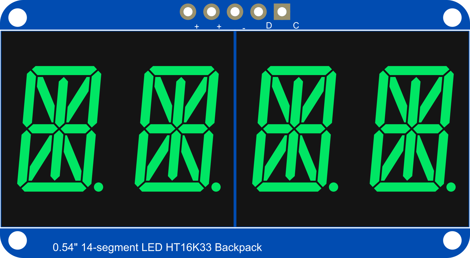
The Adafruit 14-Segment LED Alphanumeric Backpack is a versatile and easy-to-use display module capable of showing alphanumeric characters with high visibility thanks to its pure green LEDs. This module is ideal for adding a readable interface to any microcontroller project, including clocks, counters, and message displays. The I2C interface simplifies connectivity, allowing multiple displays to be controlled with just two pins.

Explore Projects Built with Adafruit 14-segment LED Alphanumeric Backpack Pure Green

Use Cirkit Designer to design, explore, and prototype these projects online. Some projects support real-time simulation. Click "Open Project" to start designing instantly!
Battery-Powered Sensor Hub with Adafruit QT Py RP2040 and OLED Display
Image of 512: A project utilizing Adafruit 14-segment LED Alphanumeric Backpack Pure Green in a practical application
This circuit features an Adafruit QT Py RP2040 microcontroller interfacing with an MPU-6050 accelerometer, an Adafruit APDS-9960 sensor, and a 0.96" OLED display via I2C communication. It is powered by a 3.7V LiPo battery and includes a green LED with a current-limiting resistor connected to an analog pin of the microcontroller.
Cirkit Designer LogoOpen Project in Cirkit Designer
Battery-Powered Smart Light with Proximity Sensor and OLED Display using Adafruit QT Py RP2040
Image of lab: A project utilizing Adafruit 14-segment LED Alphanumeric Backpack Pure Green in a practical application
This circuit is a portable, battery-powered system featuring an Adafruit QT Py RP2040 microcontroller that interfaces with an OLED display, a proximity sensor, an accelerometer, and an RGB LED strip. The system is powered by a lithium-ion battery with a step-up boost converter to provide 5V for the LED strip, and it includes a toggle switch for power control. The microcontroller communicates with the sensors and display via I2C.
Cirkit Designer LogoOpen Project in Cirkit Designer
ESP32-Based Smart Weather Station with LED Display and Multiple Sensors
Image of Copy of Zegarek: A project utilizing Adafruit 14-segment LED Alphanumeric Backpack Pure Green in a practical application
This circuit is a multi-sensor data acquisition system using an ESP32 microcontroller. It integrates various sensors including a BH1750 light sensor, BMP280 pressure sensor, DS3231 RTC, and DS18B20 temperature sensor, and displays data on a series of MAX7219 8x8 LED matrices. The system is powered via USB and includes a green LED indicator.
Cirkit Designer LogoOpen Project in Cirkit Designer
Arduino Nano Controlled Joystick and Rotary Encoder Interface with OLED Display and Multi-Color LED Feedback
Image of Blinking LED  with joystick: A project utilizing Adafruit 14-segment LED Alphanumeric Backpack Pure Green in a practical application
This circuit features an Arduino Nano interfaced with a joystick module, a rotary encoder, an OLED display, and multiple LEDs with current-limiting resistors. The joystick controls the selection of LED colors and toggles a blinking mode, while the rotary encoder adjusts the brightness of the LEDs and toggles their on/off state. The OLED display provides real-time feedback on the LED color, brightness level, and mode, enhancing user interaction.
Cirkit Designer LogoOpen Project in Cirkit Designer

Explore Projects Built with Adafruit 14-segment LED Alphanumeric Backpack Pure Green

Use Cirkit Designer to design, explore, and prototype these projects online. Some projects support real-time simulation. Click "Open Project" to start designing instantly!
Image of 512: A project utilizing Adafruit 14-segment LED Alphanumeric Backpack Pure Green in a practical application
Battery-Powered Sensor Hub with Adafruit QT Py RP2040 and OLED Display
This circuit features an Adafruit QT Py RP2040 microcontroller interfacing with an MPU-6050 accelerometer, an Adafruit APDS-9960 sensor, and a 0.96" OLED display via I2C communication. It is powered by a 3.7V LiPo battery and includes a green LED with a current-limiting resistor connected to an analog pin of the microcontroller.
Cirkit Designer LogoOpen Project in Cirkit Designer
Image of lab: A project utilizing Adafruit 14-segment LED Alphanumeric Backpack Pure Green in a practical application
Battery-Powered Smart Light with Proximity Sensor and OLED Display using Adafruit QT Py RP2040
This circuit is a portable, battery-powered system featuring an Adafruit QT Py RP2040 microcontroller that interfaces with an OLED display, a proximity sensor, an accelerometer, and an RGB LED strip. The system is powered by a lithium-ion battery with a step-up boost converter to provide 5V for the LED strip, and it includes a toggle switch for power control. The microcontroller communicates with the sensors and display via I2C.
Cirkit Designer LogoOpen Project in Cirkit Designer
Image of Copy of Zegarek: A project utilizing Adafruit 14-segment LED Alphanumeric Backpack Pure Green in a practical application
ESP32-Based Smart Weather Station with LED Display and Multiple Sensors
This circuit is a multi-sensor data acquisition system using an ESP32 microcontroller. It integrates various sensors including a BH1750 light sensor, BMP280 pressure sensor, DS3231 RTC, and DS18B20 temperature sensor, and displays data on a series of MAX7219 8x8 LED matrices. The system is powered via USB and includes a green LED indicator.
Cirkit Designer LogoOpen Project in Cirkit Designer
Image of Blinking LED  with joystick: A project utilizing Adafruit 14-segment LED Alphanumeric Backpack Pure Green in a practical application
Arduino Nano Controlled Joystick and Rotary Encoder Interface with OLED Display and Multi-Color LED Feedback
This circuit features an Arduino Nano interfaced with a joystick module, a rotary encoder, an OLED display, and multiple LEDs with current-limiting resistors. The joystick controls the selection of LED colors and toggles a blinking mode, while the rotary encoder adjusts the brightness of the LEDs and toggles their on/off state. The OLED display provides real-time feedback on the LED color, brightness level, and mode, enhancing user interaction.
Cirkit Designer LogoOpen Project in Cirkit Designer

Common Applications and Use Cases

  • Digital clocks and timers
  • Counter displays
  • Message boards
  • User interfaces for projects
  • Readouts for sensors and other devices

Technical Specifications

Key Technical Details

  • Display Color: Pure Green
  • Operating Voltage: 2.3V to 5.5V
  • Max Current (per segment): 80mA
  • I2C Interface Address Range: 0x70 - 0x77 (selectable with solder jumpers)
  • Dimensions: 1.4" x 1.75" x 0.25" (without headers)

Pin Configuration and Descriptions

Pin Description
GND Ground connection
VCC Power supply (2.3V to 5.5V)
SDA I2C data line
SCL I2C clock line

Usage Instructions

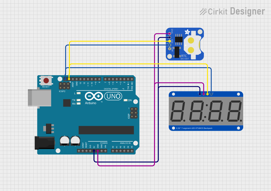
Connecting to a Circuit

  1. Connect the GND pin to the ground of your microcontroller.
  2. Connect the VCC pin to a 2.3V to 5.5V power supply.
  3. Connect the SDA and SCL pins to the I2C data and clock lines on your microcontroller.

Important Considerations and Best Practices

  • Ensure that the power supply voltage does not exceed 5.5V to prevent damage.
  • Use pull-up resistors on the I2C data and clock lines if your microcontroller does not have built-in pull-ups.
  • To avoid ghosting or flickering, ensure that the refresh rate is high enough when multiplexing displays.
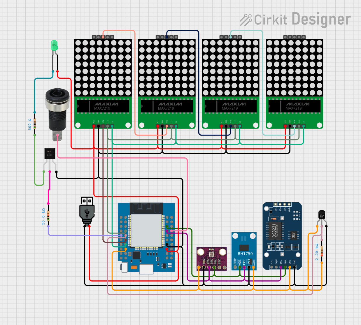
  • When chaining multiple displays, ensure that each display has a unique I2C address by setting the solder jumpers on the back of the PCB.

Example Code for Arduino UNO

#include <Wire.h>
#include <Adafruit_GFX.h>
#include <Adafruit_LEDBackpack.h>

Adafruit_AlphaNum4 alpha4 = Adafruit_AlphaNum4();

void setup() {
  alpha4.begin(0x70);  // Initialize the display with the I2C address 0x70
}

void loop() {
  alpha4.writeDigitAscii(0, 'A');  // Display 'A' on the first digit
  alpha4.writeDigitAscii(1, 'd');  // Display 'd' on the second digit
  alpha4.writeDigitAscii(2, 'a');  // Display 'a' on the third digit
  alpha4.writeDigitAscii(3, 'F');  // Display 'F' on the fourth digit
  alpha4.writeDisplay();           // Send the data to the display
  delay(1000);                     // Wait for a second
}

Troubleshooting and FAQs

Common Issues

  • Display Not Lighting Up: Check the power connections and ensure that the voltage is within the specified range. Also, verify that the I2C address matches the one in your code.
  • Characters Not Displaying Correctly: Ensure that the library is correctly installed and that the I2C lines are properly connected with pull-up resistors if needed.
  • Dim Display: Check if the current limit is too low or if the power supply voltage is insufficient.

Solutions and Tips for Troubleshooting

  • Double-check wiring, especially the I2C connections.
  • Use the i2cdetect utility or similar tools to confirm that the display is detected on the I2C bus.
  • Adjust the brightness setting in your code if the display is too dim or too bright.
  • If using multiple displays, ensure that each one has a unique I2C address.

FAQs

Q: Can I use this display with a 3.3V system? A: Yes, the display operates from 2.3V to 5.5V, making it compatible with both 3.3V and 5V systems.

Q: How many of these displays can I chain together? A: You can chain up to eight displays together, each with a unique I2C address set by the solder jumpers.

Q: Do I need to install any libraries to use this display with an Arduino? A: Yes, you will need to install the Adafruit_GFX and Adafruit_LEDBackpack libraries, which are available through the Arduino Library Manager.

Q: Can I display special characters or symbols? A: The 14-segment display can show a wide range of characters and symbols. Check the library documentation for supported characters.