Cirkit Designer Logo
Cirkit Designer
Your all-in-one circuit design IDE
Home / 
Component Documentation

How to Use Sensor Arus (ACS712-30A): Examples, Pinouts, and Specs

Image of Sensor Arus (ACS712-30A)
Cirkit Designer LogoDesign with Sensor Arus (ACS712-30A) in Cirkit Designer

Introduction

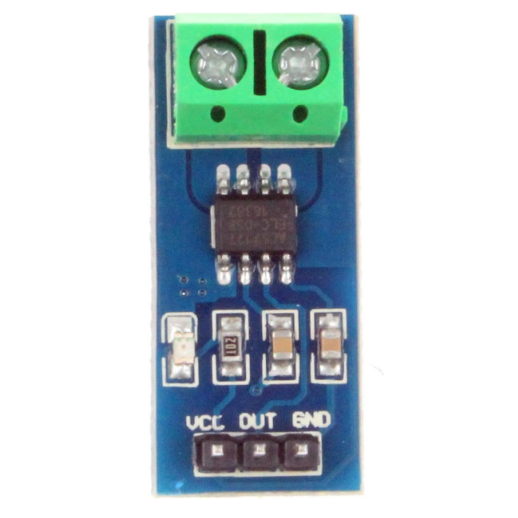
The ACS712-30A is a Hall effect-based linear current sensor designed to measure both AC and DC currents up to ±30A. It outputs an analog voltage proportional to the current flowing through the conductor, enabling precise current monitoring. The sensor is compact, easy to use, and widely employed in power monitoring, motor control, and overcurrent protection systems.

Explore Projects Built with Sensor Arus (ACS712-30A)

Use Cirkit Designer to design, explore, and prototype these projects online. Some projects support real-time simulation. Click "Open Project" to start designing instantly!
ESP32-Based Current Monitoring and Temperature Sensing System
Image of SISTEMA DE MONITOREO: A project utilizing Sensor Arus (ACS712-30A) in a practical application
This circuit is designed to measure current using an ACS712 Current Sensor and temperature using a DS18B20 sensor, with an ESP32 microcontroller to process and possibly communicate the sensor data. The ACS712 sensor output is connected to one of the ESP32's analog input pins (D34), while the DS18B20's signal line is interfaced with a digital input pin (D23) through a pull-up resistor (4.7k Ohms). The ESP32 is powered through its Vin pin, and both sensors share a common ground with the ESP32.
Cirkit Designer LogoOpen Project in Cirkit Designer
Wemos S2 Mini Controlled Smart Device with OLED Display, Thermal Printing, and RGB LED Strip
Image of DT NEA - Noah Patel: A project utilizing Sensor Arus (ACS712-30A) in a practical application
This circuit features a Wemos S2 Mini microcontroller that controls a WS2812 RGB LED strip and communicates with a 0.96" OLED display and a 58mm mini thermal printer. The ACS712 Current Sensor is interfaced with the microcontroller to monitor current, and power is managed by a CD42 BMS connected to two 18650 Li-ion batteries, with a USB-C PD Trigger Board for power delivery. The circuit is designed for visual output (LED strip, OLED display), printing capabilities, and current sensing, likely for a portable, battery-powered monitoring and display device.
Cirkit Designer LogoOpen Project in Cirkit Designer
Arduino and GSM-Based Power Monitoring and Wi-Fi Controlled Lighting System
Image of light monitoring system: A project utilizing Sensor Arus (ACS712-30A) in a practical application
This circuit is designed to monitor voltage and current using ACS712 current sensors and voltage sensors, calculate power, and control lighting via relay modules. It features an Arduino Uno R3 for processing sensor data and executing control logic, which includes sending alerts via a GSM module (sim 800l) if power falls below a threshold and connecting to WiFi using an ESP8266 module. The circuit also includes a battery with a charging module (TP4056), a step-up boost converter, and multiple AC power supplies with circuit breakers for safety.
Cirkit Designer LogoOpen Project in Cirkit Designer
ESP32-Controlled Smart Lighting System with Power Monitoring
Image of Energy Monitoring System: A project utilizing Sensor Arus (ACS712-30A) in a practical application
This circuit appears to be a multi-channel current monitoring system using several ACS712 current sensors to measure the current through different loads, likely bulbs connected to a 220V power source. The current readings from the sensors are digitized by an Adafruit ADS1115 16-bit ADC, which interfaces with an ESP32 microcontroller via I2C communication for further processing or telemetry. A buck converter is used to step down the voltage to power the ESP32 and the sensors, and the system is powered through a 2.1mm DC barrel jack, indicating it is designed for external power supply.
Cirkit Designer LogoOpen Project in Cirkit Designer

Explore Projects Built with Sensor Arus (ACS712-30A)

Use Cirkit Designer to design, explore, and prototype these projects online. Some projects support real-time simulation. Click "Open Project" to start designing instantly!
Image of SISTEMA DE MONITOREO: A project utilizing Sensor Arus (ACS712-30A) in a practical application
ESP32-Based Current Monitoring and Temperature Sensing System
This circuit is designed to measure current using an ACS712 Current Sensor and temperature using a DS18B20 sensor, with an ESP32 microcontroller to process and possibly communicate the sensor data. The ACS712 sensor output is connected to one of the ESP32's analog input pins (D34), while the DS18B20's signal line is interfaced with a digital input pin (D23) through a pull-up resistor (4.7k Ohms). The ESP32 is powered through its Vin pin, and both sensors share a common ground with the ESP32.
Cirkit Designer LogoOpen Project in Cirkit Designer
Image of DT NEA - Noah Patel: A project utilizing Sensor Arus (ACS712-30A) in a practical application
Wemos S2 Mini Controlled Smart Device with OLED Display, Thermal Printing, and RGB LED Strip
This circuit features a Wemos S2 Mini microcontroller that controls a WS2812 RGB LED strip and communicates with a 0.96" OLED display and a 58mm mini thermal printer. The ACS712 Current Sensor is interfaced with the microcontroller to monitor current, and power is managed by a CD42 BMS connected to two 18650 Li-ion batteries, with a USB-C PD Trigger Board for power delivery. The circuit is designed for visual output (LED strip, OLED display), printing capabilities, and current sensing, likely for a portable, battery-powered monitoring and display device.
Cirkit Designer LogoOpen Project in Cirkit Designer
Image of light monitoring system: A project utilizing Sensor Arus (ACS712-30A) in a practical application
Arduino and GSM-Based Power Monitoring and Wi-Fi Controlled Lighting System
This circuit is designed to monitor voltage and current using ACS712 current sensors and voltage sensors, calculate power, and control lighting via relay modules. It features an Arduino Uno R3 for processing sensor data and executing control logic, which includes sending alerts via a GSM module (sim 800l) if power falls below a threshold and connecting to WiFi using an ESP8266 module. The circuit also includes a battery with a charging module (TP4056), a step-up boost converter, and multiple AC power supplies with circuit breakers for safety.
Cirkit Designer LogoOpen Project in Cirkit Designer
Image of Energy Monitoring System: A project utilizing Sensor Arus (ACS712-30A) in a practical application
ESP32-Controlled Smart Lighting System with Power Monitoring
This circuit appears to be a multi-channel current monitoring system using several ACS712 current sensors to measure the current through different loads, likely bulbs connected to a 220V power source. The current readings from the sensors are digitized by an Adafruit ADS1115 16-bit ADC, which interfaces with an ESP32 microcontroller via I2C communication for further processing or telemetry. A buck converter is used to step down the voltage to power the ESP32 and the sensors, and the system is powered through a 2.1mm DC barrel jack, indicating it is designed for external power supply.
Cirkit Designer LogoOpen Project in Cirkit Designer

Common Applications

  • Power consumption monitoring in appliances
  • Battery management systems
  • Motor current sensing
  • Overcurrent protection in circuits
  • Renewable energy systems (e.g., solar inverters)

Technical Specifications

Below are the key technical details of the ACS712-30A sensor:

Parameter Value
Supply Voltage (Vcc) 4.5V to 5.5V
Current Measurement Range ±30A
Sensitivity 66mV/A
Output Voltage at 0A Vcc/2 (typically 2.5V at 5V Vcc)
Response Time 5 µs
Bandwidth 80 kHz
Operating Temperature -40°C to 85°C
Dimensions 31mm x 13mm x 15mm

Pin Configuration and Descriptions

The ACS712-30A module typically has three pins for interfacing:

Pin Name Description
1 Vcc Power supply input (4.5V to 5.5V)
2 Out Analog voltage output proportional to the current
3 GND Ground connection

Usage Instructions

How to Use the ACS712-30A in a Circuit

  1. Power the Sensor: Connect the Vcc pin to a 5V power supply and the GND pin to the ground.
  2. Connect the Load: Pass the conductor carrying the current to be measured through the sensor's onboard current path (IP+ and IP- terminals).
  3. Read the Output: The Out pin provides an analog voltage proportional to the current. At 0A, the output voltage is approximately 2.5V (assuming a 5V supply). The voltage increases or decreases linearly with positive or negative currents, respectively.

Important Considerations

  • Calibration: The sensor's output may vary slightly due to manufacturing tolerances. Calibrate the sensor in your application for accurate measurements.
  • Noise Filtering: Add a capacitor (e.g., 0.1µF) between the Out pin and GND to reduce noise in the output signal.
  • Current Path: Ensure the current-carrying conductor is securely connected to the IP+ and IP- terminals for accurate readings.
  • Avoid Overcurrent: Do not exceed the ±30A current rating to prevent damage to the sensor.

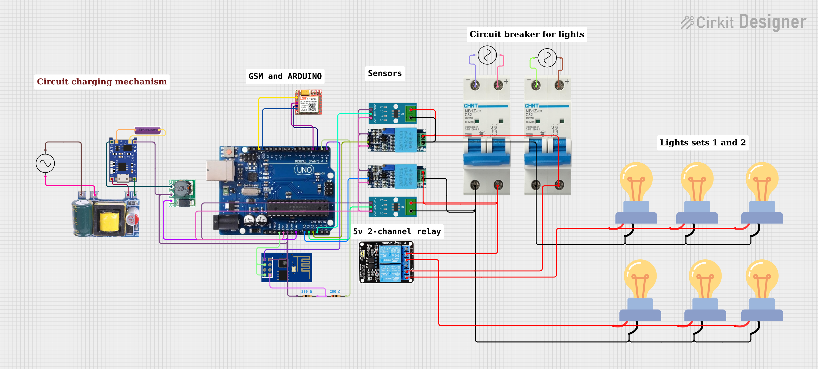
Example: Using ACS712-30A with Arduino UNO

Below is an example code to read current values using the ACS712-30A sensor and an Arduino UNO:

// Include necessary libraries (if any)

// Define the analog pin connected to the ACS712 output
const int sensorPin = A0;

// Define the sensitivity of the ACS712-30A (66mV per Amp)
const float sensitivity = 0.066; // 66mV/A

// Define the supply voltage (Vcc) and zero-current voltage
const float Vcc = 5.0; // Supply voltage in volts
const float zeroCurrentVoltage = Vcc / 2; // 2.5V at 0A

void setup() {
  Serial.begin(9600); // Initialize serial communication
  pinMode(sensorPin, INPUT); // Set the sensor pin as input
}

void loop() {
  // Read the analog value from the sensor
  int sensorValue = analogRead(sensorPin);

  // Convert the analog value to voltage
  float sensorVoltage = (sensorValue / 1023.0) * Vcc;

  // Calculate the current in Amperes
  float current = (sensorVoltage - zeroCurrentVoltage) / sensitivity;

  // Print the current value to the Serial Monitor
  Serial.print("Current: ");
  Serial.print(current);
  Serial.println(" A");

  delay(500); // Wait for 500ms before the next reading
}

Notes:

  • Ensure the Arduino's GND is connected to the sensor's GND.
  • Use a stable 5V power supply for accurate readings.

Troubleshooting and FAQs

Common Issues and Solutions

  1. No Output or Incorrect Readings

    • Cause: Improper wiring or loose connections.
    • Solution: Double-check all connections, especially the Vcc, GND, and Out pins.
  2. High Noise in Output

    • Cause: Electrical noise or lack of filtering.
    • Solution: Add a 0.1µF capacitor between the Out pin and GND to filter noise.
  3. Output Voltage Not Centered at 2.5V

    • Cause: Sensor calibration or supply voltage variation.
    • Solution: Verify the supply voltage is stable at 5V. Perform a calibration to adjust for offsets.
  4. Sensor Overheating

    • Cause: Current exceeding the ±30A limit.
    • Solution: Ensure the current through the sensor does not exceed its rated range.

FAQs

Q1: Can the ACS712-30A measure currents below 1A?
Yes, but the resolution may be limited due to the sensor's sensitivity (66mV/A). For higher precision at low currents, consider a lower-range ACS712 variant (e.g., ACS712-5A).

Q2: Can I use the ACS712-30A with a 3.3V microcontroller?
Yes, but the output voltage range will be limited, and the zero-current voltage will be 1.65V (Vcc/2). Ensure the microcontroller's ADC can handle the reduced range.

Q3: Is the ACS712-30A suitable for high-frequency AC currents?
The sensor has a bandwidth of 80kHz, making it suitable for most AC applications. However, for very high-frequency currents, additional filtering may be required.

Q4: How do I protect the sensor from overcurrent?
Use a fuse or circuit breaker in series with the current path to prevent damage from excessive currents.