How to Use DP30V5A: Examples, Pinouts, and Specs
Introduction
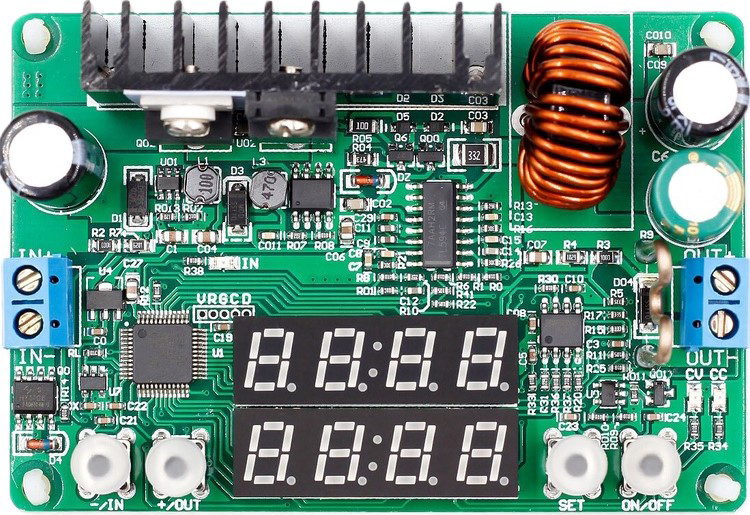
The DP30V5A is a programmable DC power supply designed to provide adjustable voltage and current outputs. It is widely used in laboratories, development environments, and testing setups for powering and evaluating electronic devices. With its precise control and digital interface, the DP30V5A is ideal for applications requiring stable and customizable power delivery.
Explore Projects Built with DP30V5A


Explore Projects Built with DP30V5A
Common Applications and Use Cases
- Powering and testing electronic circuits and devices
- Laboratory experiments and research
- Development and debugging of embedded systems
- Battery charging and testing
- Educational purposes in electronics training
Technical Specifications
The DP30V5A offers a range of features and specifications that make it versatile and reliable for various applications.
Key Technical Details
| Parameter | Specification |
|---|---|
| Input Voltage | 110V/220V AC (switchable) |
| Output Voltage Range | 0V to 30V DC |
| Output Current Range | 0A to 5A DC |
| Voltage Resolution | 0.01V |
| Current Resolution | 0.001A |
| Display Type | Digital (LED or LCD) |
| Voltage Accuracy | ±0.5% |
| Current Accuracy | ±0.5% |
| Protection Features | Over-voltage, over-current, and short-circuit protection |
| Communication Interface | USB or UART (optional, depending on model) |
Pin Configuration and Descriptions
The DP30V5A does not have traditional pins like an IC but instead features input and output terminals. Below is a description of its key connections:
| Terminal/Port | Description |
|---|---|
| Input AC Terminals | Connect to 110V/220V AC power source |
| Output Positive (+) | Positive DC output terminal for connecting the load |
| Output Negative (-) | Negative DC output terminal for connecting the load |
| USB/UART Port (optional) | For communication with a PC or microcontroller |
Usage Instructions
The DP30V5A is straightforward to use, but proper setup and operation are essential for optimal performance and safety.
How to Use the DP30V5A in a Circuit
- Connect the Input Power: Ensure the input voltage selector is set to the correct AC voltage (110V or 220V). Plug the power supply into an appropriate AC outlet.
- Set the Output Voltage and Current:
- Use the control knobs or buttons to adjust the desired voltage and current limits.
- Monitor the settings on the digital display.
- Connect the Load:
- Attach the positive terminal of the load to the output positive (+) terminal.
- Attach the negative terminal of the load to the output negative (-) terminal.
- Power On the Load:
- Turn on the output using the power supply's control interface.
- The load will now receive the configured voltage and current.
- Monitor and Adjust:
- Continuously monitor the output voltage and current on the display.
- Adjust the settings as needed during operation.
Important Considerations and Best Practices
- Set Current Limit: Always set an appropriate current limit to protect your load from overcurrent conditions.
- Avoid Short Circuits: Ensure proper connections to prevent short circuits, which could damage the power supply or the load.
- Ventilation: Operate the DP30V5A in a well-ventilated area to prevent overheating.
- Use Proper Cables: Use cables with adequate current-carrying capacity to avoid overheating or voltage drops.
- Communication Interface: If using the USB/UART interface, ensure proper drivers and software are installed on your PC or microcontroller.
Example: Controlling the DP30V5A with an Arduino UNO
If your DP30V5A model includes a UART interface, you can control it using an Arduino UNO. Below is an example code snippet:
#include <SoftwareSerial.h>

// Define RX and TX pins for communication with DP30V5A
SoftwareSerial dp30v5aSerial(10, 11); // RX = pin 10, TX = pin 11

void setup() {
  Serial.begin(9600); // Initialize serial monitor
  dp30v5aSerial.begin(9600); // Initialize DP30V5A communication

  // Example command to set voltage to 12.00V
  dp30v5aSerial.print("VSET1:12.00\n");
  // Example command to set current limit to 2.00A
  dp30v5aSerial.print("ISET1:2.00\n");

  Serial.println("DP30V5A configured: 12V, 2A");
}

void loop() {
  // Continuously monitor DP30V5A responses (if applicable)
  if (dp30v5aSerial.available()) {
    String response = dp30v5aSerial.readString();
    Serial.println("DP30V5A Response: " + response);
  }
}
Note: Replace the commands (
VSET1andISET1) with the appropriate protocol commands for your DP30V5A model. Refer to the manufacturer's communication protocol documentation.
Troubleshooting and FAQs
Common Issues and Solutions
| Issue | Possible Cause | Solution |
|---|---|---|
| No output voltage | Output is disabled | Enable the output using the control panel |
| Voltage or current not adjustable | Incorrect settings or faulty controls | Verify settings and check for hardware issues |
| Overload or protection triggered | Load exceeds set limits | Reduce the load or increase the limits |
| Communication failure (UART/USB) | Incorrect wiring or driver issues | Check connections and install proper drivers |
FAQs
Can I use the DP30V5A to charge batteries?
- Yes, but ensure the voltage and current limits are set according to the battery's specifications.
What happens if I short the output terminals?
- The DP30V5A includes short-circuit protection, but frequent short circuits may damage the device. Avoid intentional shorting.
How accurate are the voltage and current readings?
- The DP30V5A provides a voltage accuracy of ±0.5% and a current accuracy of ±0.5%, which is sufficient for most applications.
Can I control the DP30V5A remotely?
- Yes, if your model includes a USB or UART interface, you can control it using a PC or microcontroller.
By following this documentation, you can effectively use the DP30V5A programmable DC power supply for a wide range of applications.