
How to Use 5mm Red/Green LED (Common Cathode): Examples, Pinouts, and Specs
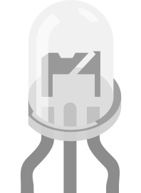
 Design with 5mm Red/Green LED (Common Cathode) in Cirkit Designer
Introduction
The 5mm Red/Green LED (Common Cathode) is a dual-color light-emitting diode that can emit either red or green light. It features a common cathode configuration, meaning both LEDs share a single cathode pin, simplifying circuit design and control. This component is widely used in status indicators, signal displays, and decorative lighting applications due to its compact size and dual-color functionality.
Explore Projects Built with 5mm Red/Green LED (Common Cathode)
 Open Project in Cirkit Designer
 Open Project in Cirkit Designer
 Open Project in Cirkit Designer
 Open Project in Cirkit Designer
Explore Projects Built with 5mm Red/Green LED (Common Cathode)
Open Project in Cirkit DesignerOpen Project in Cirkit DesignerOpen Project in Cirkit DesignerOpen Project in Cirkit DesignerCommon Applications:
- Status indicators for electronic devices
- Signal and traffic light simulations
- DIY electronics and hobby projects
- Arduino-based projects for visual feedback
- Educational tools for learning about LEDs and circuits
Technical Specifications
Below are the key technical details for the 5mm Red/Green LED (Common Cathode):
| Parameter | Value |
|---|---|
| LED Type | Dual-color (Red/Green) |
| Package Size | 5mm |
| Forward Voltage (Red) | 1.8V - 2.2V |
| Forward Voltage (Green) | 2.0V - 2.4V |
| Forward Current | 20mA (per LED) |
| Viewing Angle | 30° - 45° |
| Cathode Configuration | Common Cathode |
| Maximum Power | 50mW |
Pin Configuration:
The 5mm Red/Green LED (Common Cathode) has three pins. The table below describes each pin:
| Pin Number | Pin Name | Description |
|---|---|---|
| 1 | Anode (Red) | Connect to the positive terminal for red light. |
| 2 | Cathode | Common cathode, connect to ground (GND). |
| 3 | Anode (Green) | Connect to the positive terminal for green light. |
Usage Instructions
How to Use the Component in a Circuit
- Identify the Pins: Locate the three pins of the LED. The middle pin is the common cathode, while the other two pins are the anodes for red and green.
- Connect the Cathode: Connect the cathode (middle pin) to the ground (GND) of your circuit.
- Connect Resistors: Use current-limiting resistors (typically 220Ω to 330Ω) in series with the anodes to prevent excessive current from damaging the LEDs.
- Control the Colors:
- To light up the red LED, apply a positive voltage to the red anode pin.
- To light up the green LED, apply a positive voltage to the green anode pin.
- To alternate between colors, switch the voltage between the two anodes.
Example Circuit with Arduino UNO
Below is an example of how to connect and control the 5mm Red/Green LED (Common Cathode) using an Arduino UNO:
Circuit Connections:
- Connect the cathode (middle pin) to the GND pin of the Arduino.
- Connect the red anode pin to Arduino digital pin 9 through a 220Ω resistor.
- Connect the green anode pin to Arduino digital pin 10 through a 220Ω resistor.
Arduino Code:
// Define pin numbers for the red and green anodes
const int redPin = 9;   // Red LED anode connected to pin 9
const int greenPin = 10; // Green LED anode connected to pin 10

void setup() {
  // Set the LED pins as output
  pinMode(redPin, OUTPUT);
  pinMode(greenPin, OUTPUT);
}

void loop() {
  // Turn on the red LED and turn off the green LED
  digitalWrite(redPin, HIGH);  // Red LED ON
  digitalWrite(greenPin, LOW); // Green LED OFF
  delay(1000);                 // Wait for 1 second

  // Turn on the green LED and turn off the red LED
  digitalWrite(redPin, LOW);   // Red LED OFF
  digitalWrite(greenPin, HIGH); // Green LED ON
  delay(1000);                 // Wait for 1 second
}
Important Considerations:
- Always use appropriate current-limiting resistors to protect the LEDs.
- Avoid exceeding the maximum forward current (20mA) to prevent damage.
- Ensure proper polarity when connecting the LED to avoid reverse voltage damage.
Troubleshooting and FAQs
Common Issues and Solutions:
Neither LED Lights Up:
- Check the polarity of the connections. Ensure the cathode is connected to GND.
- Verify that the resistors are properly connected and not open-circuited.
- Confirm that the power supply voltage matches the LED's forward voltage requirements.
Only One LED Lights Up:
- Ensure the correct anode pin is connected to the power source.
- Check the resistor value for the non-functioning LED. It may be too high, limiting current excessively.
LEDs Are Dim:
- Verify the resistor values. If the resistance is too high, the current may be insufficient.
- Check the power supply voltage to ensure it meets the LED's forward voltage requirements.
LED Flickers:
- Ensure stable connections and avoid loose wires.
- If using PWM (Pulse Width Modulation) for brightness control, verify the PWM frequency is appropriate.
FAQs:
Q: Can I light up both colors simultaneously?
A: Yes, you can light up both colors by applying voltage to both anodes simultaneously. However, the resulting color will be a mix of red and green, appearing yellowish.
Q: Can I use this LED without resistors?
A: No, resistors are essential to limit the current and prevent damage to the LEDs.
Q: What happens if I reverse the polarity?
A: LEDs are polarity-sensitive. Reversing the polarity may prevent the LED from lighting up or, in some cases, damage the component.
Q: Can I control this LED with a microcontroller?
A: Yes, the 5mm Red/Green LED (Common Cathode) can be easily controlled using microcontrollers like Arduino, Raspberry Pi, or others.
By following this documentation, you can effectively use the 5mm Red/Green LED (Common Cathode) in your projects and troubleshoot common issues with ease.