How to Use INMP441: Examples, Pinouts, and Specs
Introduction
The INMP441 is a low-power, high-performance digital MEMS microphone with an I2S (Inter-IC Sound) output, manufactured by AITRIP. It is designed for high-quality audio applications, offering a compact form factor, low noise, and high sensitivity. The INMP441 is ideal for use in portable devices, voice recognition systems, and other audio capture applications where high fidelity and low power consumption are critical.
Explore Projects Built with INMP441
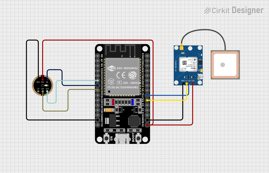
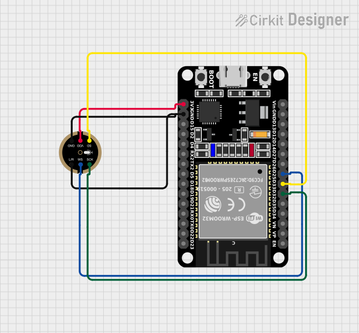
Explore Projects Built with INMP441
Common Applications
- Voice recognition systems (e.g., smart assistants)
- Audio recording devices
- IoT devices with sound detection
- Portable electronics
- Noise monitoring systems
Technical Specifications
The INMP441 is designed to deliver excellent audio performance while maintaining low power consumption. Below are its key technical specifications:
| Parameter | Value |
|---|---|
| Manufacturer | AITRIP |
| Part Number | INMP441 |
| Output Interface | I2S |
| Supply Voltage (VDD) | 1.8V to 3.3V |
| Current Consumption | 1.4 mA (typical) |
| Signal-to-Noise Ratio (SNR) | 61 dB |
| Acoustic Overload Point | 120 dB SPL |
| Sensitivity | -26 dBFS ±1 dB |
| Frequency Response | 60 Hz to 15 kHz |
| Operating Temperature | -40°C to +85°C |
| Package Dimensions | 3.5 mm × 2.65 mm × 0.98 mm |
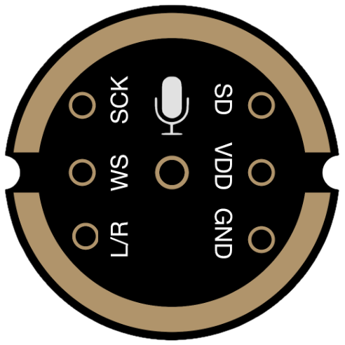
Pin Configuration and Descriptions
The INMP441 has a total of 7 pins. Below is the pinout and description:
| Pin Name | Pin Number | Description |
|---|---|---|
| VDD | 1 | Power supply input (1.8V to 3.3V). |
| GND | 2 | Ground connection. |
| WS | 3 | Word Select (I2S left/right channel selection). |
| SCK | 4 | Serial Clock (I2S clock input). |
| SD | 5 | Serial Data (I2S data output). |
| L/R | 6 | Left/Right channel select. Connect to GND for left channel, VDD for right. |
| NC | 7 | No connection. Leave unconnected or floating. |
Usage Instructions
The INMP441 is straightforward to use in digital audio applications, thanks to its I2S output. Below are the steps and considerations for integrating it into a circuit:
Circuit Connection
- Power Supply: Connect the VDD pin to a 1.8V to 3.3V power source and the GND pin to ground.
- I2S Interface:
- Connect the
SCKpin to the I2S clock line of your microcontroller or processor. - Connect the
WSpin to the I2S word select line. - Connect the
SDpin to the I2S data input line of your microcontroller.
- Connect the
- Channel Selection:
- Use the
L/Rpin to select the audio channel:- Connect to GND for the left channel.
- Connect to VDD for the right channel.
- Use the
- Leave the
NCpin unconnected.
Important Considerations
- Ensure the power supply voltage is within the specified range (1.8V to 3.3V).
- Use decoupling capacitors (e.g., 0.1 µF) near the VDD pin to reduce noise.
- The INMP441 outputs digital audio data in I2S format, so ensure your microcontroller supports I2S communication.
- Avoid exposing the microphone to excessive heat or mechanical stress during soldering.
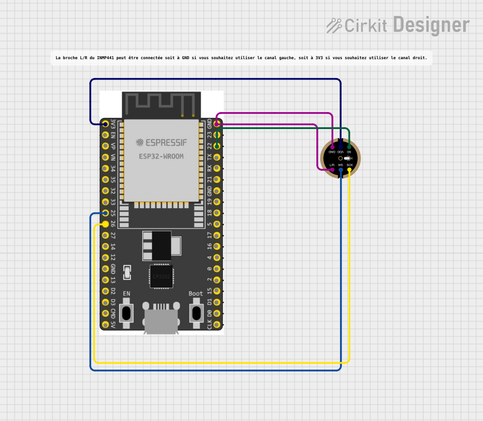
Example: Connecting INMP441 to Arduino UNO
The Arduino UNO does not natively support I2S communication. However, you can use an external I2S interface or a compatible microcontroller like the ESP32. Below is an example of using the INMP441 with an ESP32:
Wiring Diagram
| INMP441 Pin | ESP32 Pin |
|---|---|
| VDD | 3.3V |
| GND | GND |
| WS | GPIO25 |
| SCK | GPIO26 |
| SD | GPIO22 |
| L/R | GND (Left) |
Example Code
#include <driver/i2s.h>

// I2S configuration
#define I2S_NUM         I2S_NUM_0  // I2S port number
#define I2S_WS          25         // Word Select pin
#define I2S_SCK         26         // Serial Clock pin
#define I2S_SD          22         // Serial Data pin

void setup() {
  // Configure I2S
  i2s_config_t i2s_config = {
    .mode = (i2s_mode_t)(I2S_MODE_MASTER | I2S_MODE_RX), // Master mode, receive
    .sample_rate = 16000,                               // Sampling rate
    .bits_per_sample = I2S_BITS_PER_SAMPLE_16BIT,       // 16-bit audio
    .channel_format = I2S_CHANNEL_FMT_ONLY_LEFT,        // Left channel only
    .communication_format = I2S_COMM_FORMAT_I2S,       // I2S format
    .intr_alloc_flags = 0,                             // Default interrupt priority
    .dma_buf_count = 8,                                // Number of DMA buffers
    .dma_buf_len = 64                                  // Size of each DMA buffer
  };

  // Configure I2S pins
  i2s_pin_config_t pin_config = {
    .bck_io_num = I2S_SCK,  // Serial Clock
    .ws_io_num = I2S_WS,    // Word Select
    .data_out_num = -1,     // Not used (output)
    .data_in_num = I2S_SD   // Serial Data (input)
  };

  // Install and start I2S driver
  i2s_driver_install(I2S_NUM, &i2s_config, 0, NULL);
  i2s_set_pin(I2S_NUM, &pin_config);
}

void loop() {
  // Buffer to store audio data
  uint8_t audio_data[128];
  size_t bytes_read;

  // Read audio data from INMP441
  i2s_read(I2S_NUM, audio_data, sizeof(audio_data), &bytes_read, portMAX_DELAY);

  // Process audio data (e.g., send to a server or save to storage)
}
Troubleshooting and FAQs
Common Issues
No Audio Data Received:
- Ensure the I2S pins are correctly connected to the microcontroller.
- Verify that the microcontroller supports I2S communication.
- Check the power supply voltage (1.8V to 3.3V).
Distorted Audio:
- Verify the sampling rate and bit depth match the INMP441's capabilities.
- Ensure the microphone is not exposed to excessive noise or vibrations.
Microphone Not Detected:
- Check the
L/Rpin configuration for proper channel selection. - Ensure the
SCKandWSsignals are being generated by the microcontroller.
- Check the
Tips for Troubleshooting
- Use an oscilloscope to verify the I2S clock and data signals.
- Test the microphone with a known working I2S device to rule out hardware issues.
- Double-check all connections and solder joints for continuity.
By following this documentation, you can successfully integrate the INMP441 into your audio projects and achieve high-quality sound capture.