How to Use USB C Male Charger Board: Examples, Pinouts, and Specs
Introduction
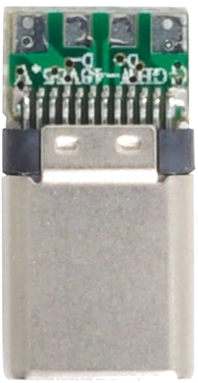
The USB C Male Charger Board is a compact circuit board designed to enable charging and data transfer for devices using a USB Type-C connection. It integrates power management features to ensure safe and efficient charging, making it ideal for DIY electronics projects, prototyping, and custom device designs. This board is widely used in applications such as portable power banks, battery charging circuits, and USB-powered devices.
Explore Projects Built with USB C Male Charger Board


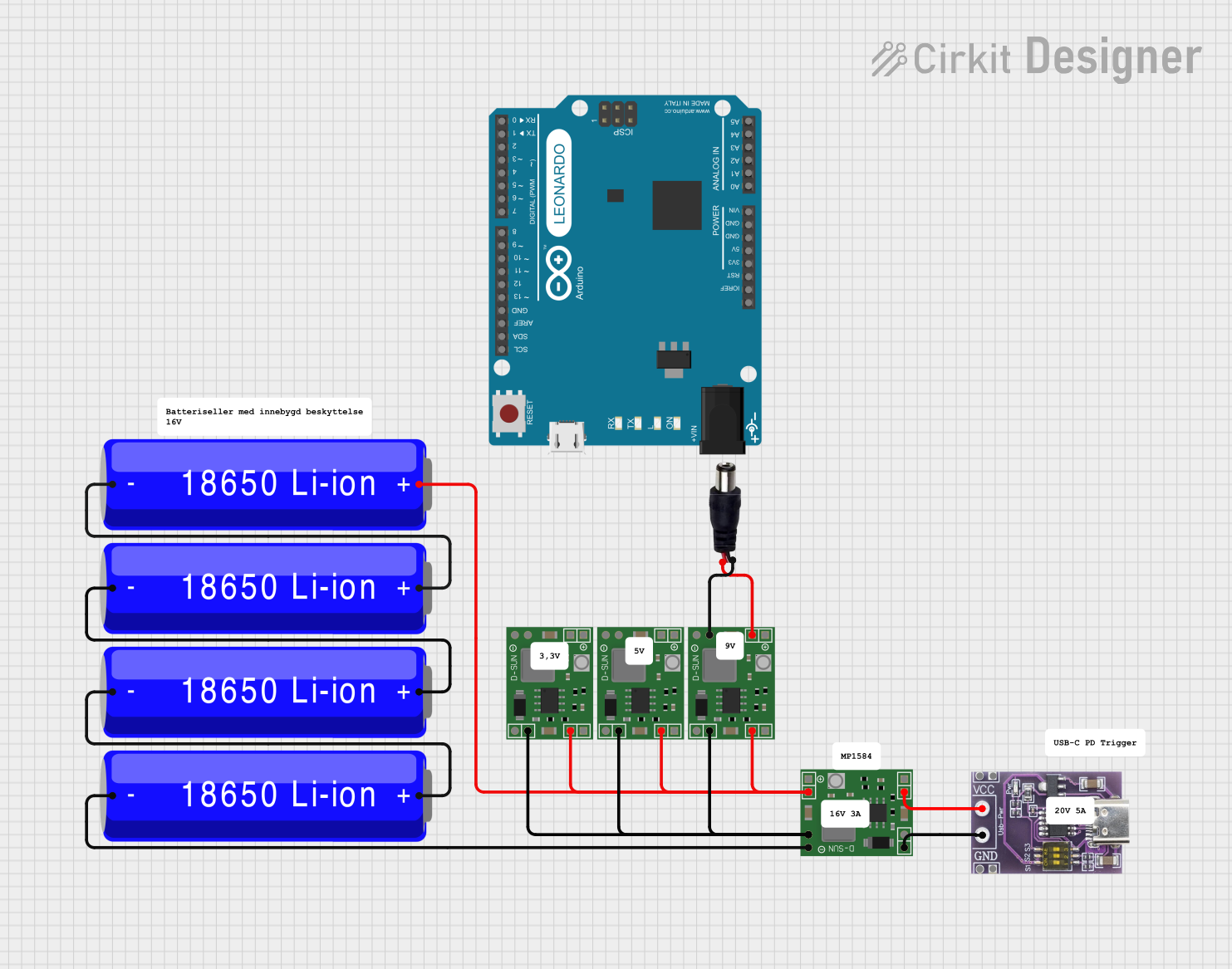
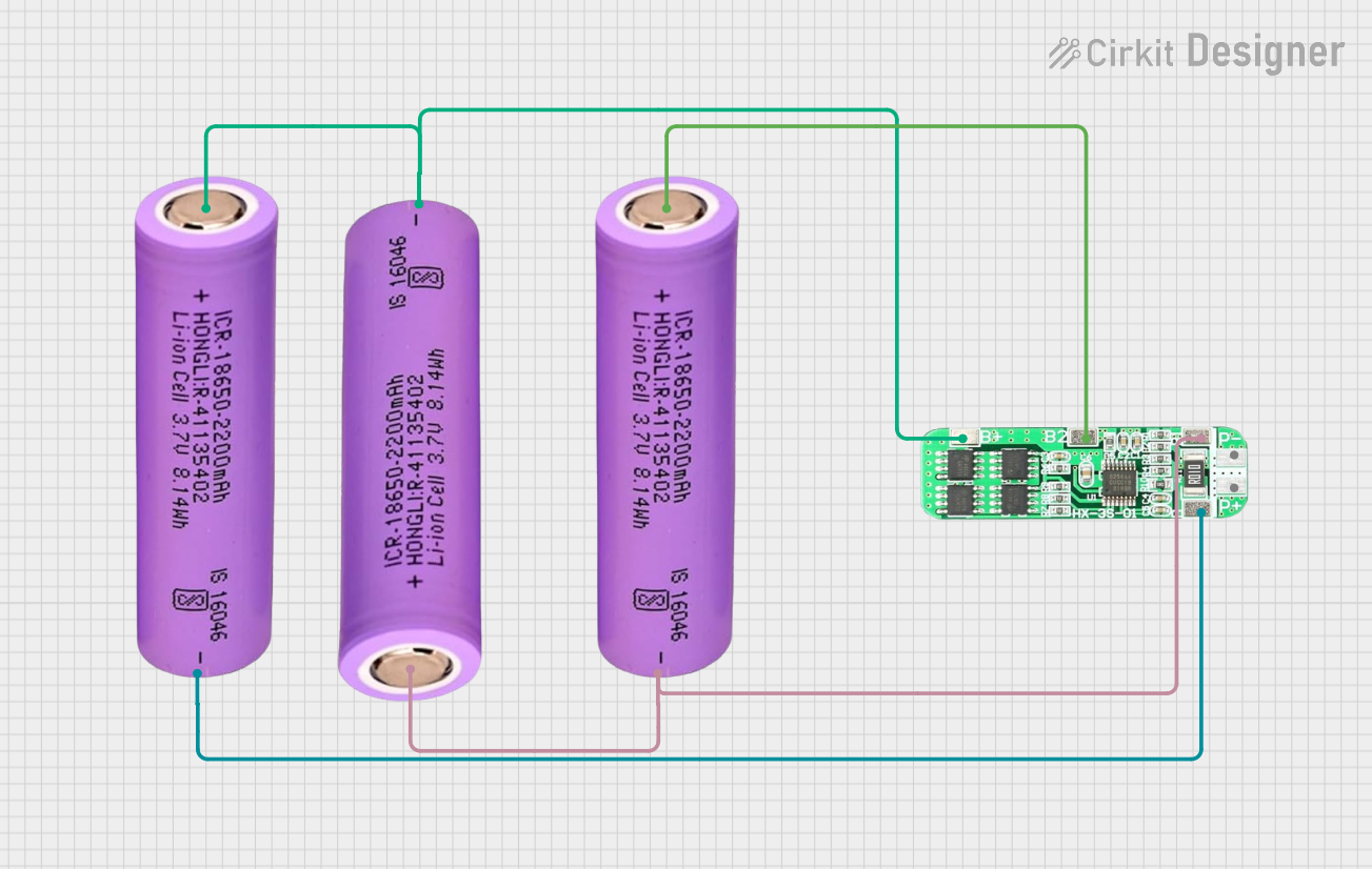
Explore Projects Built with USB C Male Charger Board
Common Applications:
- Charging lithium-ion or lithium-polymer batteries
- Powering small electronic devices
- USB Type-C data communication for embedded systems
- DIY projects requiring USB Type-C connectivity
Technical Specifications
Below are the key technical details of the USB C Male Charger Board:
| Parameter | Specification |
|---|---|
| Input Voltage | 5V (via USB Type-C connector) |
| Output Voltage | 5V |
| Maximum Output Current | 3A |
| Connector Type | USB Type-C Male |
| Board Dimensions | Typically 25mm x 15mm (varies by model) |
| Power Management | Overcurrent and overvoltage protection |
| Data Transfer Support | USB 2.0 or USB 3.0 (depending on model) |
Pin Configuration and Descriptions
The USB C Male Charger Board typically features the following pins or solder pads:
| Pin Name | Description |
|---|---|
| VBUS | 5V power input/output from the USB Type-C connector. |
| GND | Ground connection for the circuit. |
| D+ | Data+ line for USB communication. |
| D- | Data- line for USB communication. |
| ID | Identification pin for USB Type-C (optional, used in some models). |
| CC1/CC2 | Configuration Channel pins for USB Type-C power negotiation (optional). |
Note: The exact pinout may vary depending on the specific model of the USB C Male Charger Board. Always refer to the manufacturer's datasheet for precise details.
Usage Instructions
How to Use the USB C Male Charger Board in a Circuit
Power Input:
- Connect the USB Type-C male connector to a power source (e.g., a USB wall adapter or power bank).
- Ensure the input voltage is 5V to avoid damaging the board.
Power Output:
- Use the VBUS and GND pins to power your circuit or charge a battery.
- If charging a lithium-ion battery, ensure you use a proper charging IC or circuit to regulate the charging process.
Data Communication:
- Connect the D+ and D- pins to the corresponding data lines of your microcontroller or device for USB communication.
- Ensure proper termination and impedance matching for reliable data transfer.
Mounting:
- Secure the board in your project using screws, adhesive, or a custom enclosure to prevent accidental disconnections.
Important Considerations and Best Practices
- Current Limitation: Do not exceed the maximum output current (3A) to avoid overheating or damaging the board.
- Heat Dissipation: If operating at high currents, ensure adequate ventilation or heat sinking to prevent thermal issues.
- Data Lines: For reliable USB communication, keep the D+ and D- lines as short as possible and avoid running them near high-power traces.
- Polarity: Double-check all connections to avoid reverse polarity, which can damage the board and connected devices.
Example: Using with Arduino UNO
The USB C Male Charger Board can be used to power an Arduino UNO. Below is an example of how to connect it:
- Connect the VBUS pin of the charger board to the 5V pin of the Arduino UNO.
- Connect the GND pin of the charger board to the GND pin of the Arduino UNO.
- Optionally, use the D+ and D- pins for USB communication if required.
Here is a simple Arduino sketch to blink an LED while powered by the USB C Male Charger Board:
// Simple LED Blink Example
// This code blinks an LED connected to pin 13 of the Arduino UNO.

void setup() {
  pinMode(13, OUTPUT); // Set pin 13 as an output
}

void loop() {
  digitalWrite(13, HIGH); // Turn the LED on
  delay(1000);            // Wait for 1 second
  digitalWrite(13, LOW);  // Turn the LED off
  delay(1000);            // Wait for 1 second
}
Note: Ensure the USB C Male Charger Board is providing a stable 5V output to the Arduino UNO.
Troubleshooting and FAQs
Common Issues and Solutions
Board Overheating:
- Cause: Excessive current draw or poor ventilation.
- Solution: Reduce the load current or improve airflow around the board.
No Power Output:
- Cause: Faulty USB cable or improper connections.
- Solution: Check the USB cable and ensure all connections are secure.
Data Transfer Issues:
- Cause: Incorrect wiring of D+ and D- lines or interference.
- Solution: Verify the data line connections and minimize interference by keeping data lines short.
Device Not Charging:
- Cause: Incompatible device or insufficient current.
- Solution: Ensure the device supports 5V charging and does not exceed the board's current limit.
FAQs
Q1: Can this board be used to charge a 3.7V lithium-ion battery?
A1: Yes, but you must use a dedicated lithium-ion battery charging IC (e.g., TP4056) to regulate the charging process.
Q2: Does this board support fast charging?
A2: Some models may support fast charging if they include USB Power Delivery (PD) or Quick Charge (QC) features. Check the specific model's datasheet.
Q3: Can I use this board for USB 3.0 data transfer?
A3: Only if the board explicitly supports USB 3.0. Otherwise, it will default to USB 2.0 speeds.
Q4: Is reverse polarity protection included?
A4: Most boards include basic protection, but it is recommended to verify this in the datasheet or add external protection if needed.
By following this documentation, you can effectively integrate the USB C Male Charger Board into your projects and troubleshoot common issues.