How to Use ESP32 WROOM-32 C Type CP2102 USB Dual Core WiFi + Bluetooth 38 Pins: Examples, Pinouts, and Specs
Introduction
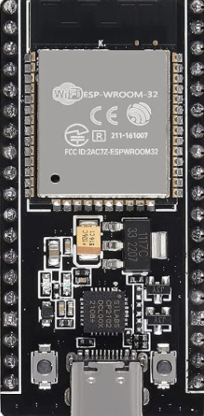
The ESP32 WROOM-32 C Type is a high-performance microcontroller module manufactured by ESP32. It features a dual-core processor, integrated WiFi and Bluetooth capabilities, and a CP2102 USB interface for seamless programming and connectivity. With 38 GPIO pins, this module is highly versatile and suitable for a wide range of IoT, automation, and embedded system applications.
Explore Projects Built with ESP32 WROOM-32 C Type CP2102 USB Dual Core WiFi + Bluetooth 38 Pins


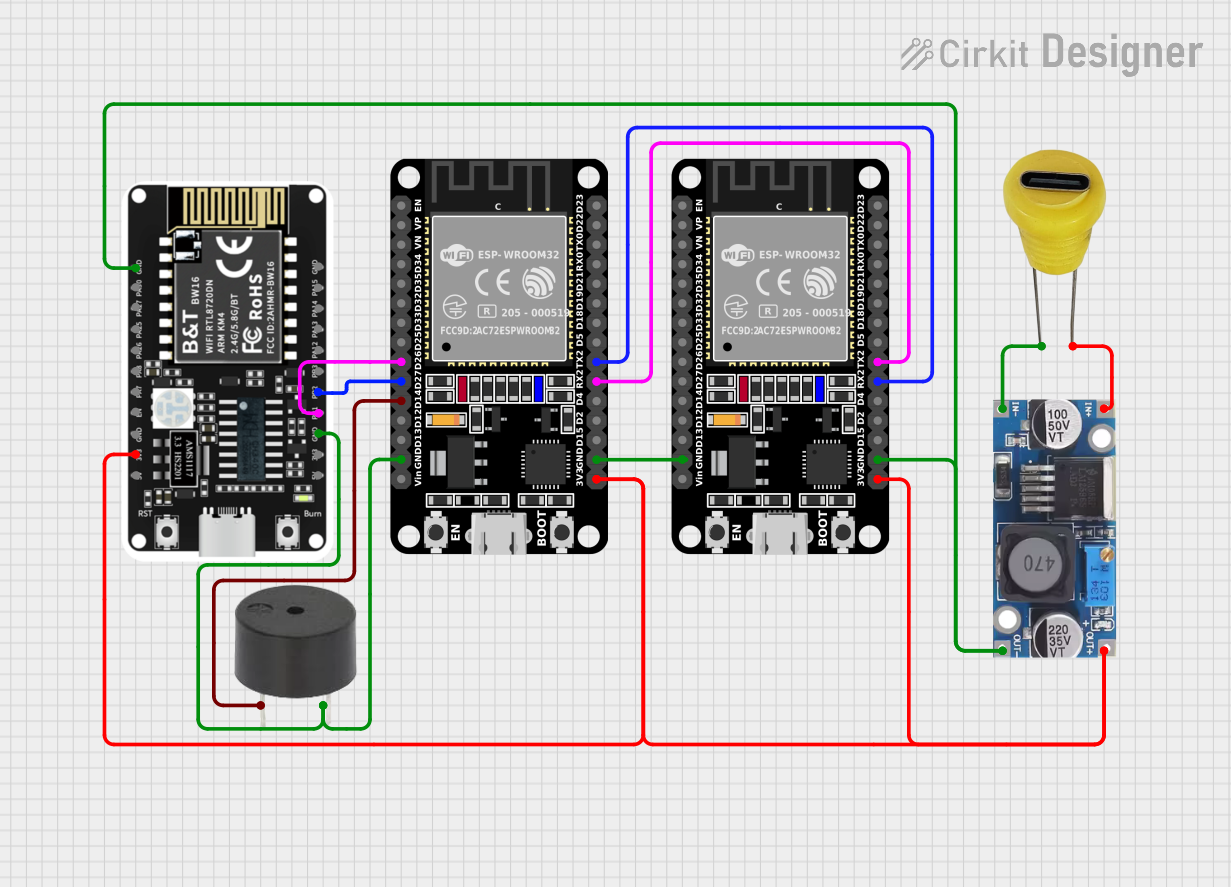
Explore Projects Built with ESP32 WROOM-32 C Type CP2102 USB Dual Core WiFi + Bluetooth 38 Pins
Common Applications and Use Cases
- IoT devices and smart home automation
- Wireless sensor networks
- Wearable technology
- Robotics and drones
- Industrial automation
- Prototyping and development of connected devices
Technical Specifications
The following table outlines the key technical details of the ESP32 WROOM-32 C Type module:
| Specification | Details |
|---|---|
| Manufacturer | ESP32 |
| Part ID | ESP32-Wroom-38-C-Type |
| Processor | Dual-core Xtensa® 32-bit LX6 |
| Clock Speed | Up to 240 MHz |
| Flash Memory | 4 MB |
| SRAM | 520 KB |
| Wireless Connectivity | WiFi 802.11 b/g/n, Bluetooth v4.2 + BLE |
| USB Interface | CP2102 USB-to-UART bridge |
| Operating Voltage | 3.3V |
| GPIO Pins | 38 |
| ADC Channels | 18 |
| DAC Channels | 2 |
| PWM Outputs | 16 |
| Communication Protocols | UART, SPI, I2C, I2S, CAN, Ethernet MAC |
| Operating Temperature | -40°C to +85°C |
| Dimensions | 25.5 mm x 18 mm |
Pin Configuration and Descriptions
The ESP32 WROOM-32 C Type module has 38 pins. Below is a table summarizing the pin configuration:
| Pin Number | Pin Name | Description |
|---|---|---|
| 1 | EN | Enable pin (active high) to reset the module |
| 2 | IO0 | GPIO0, used for boot mode selection |
| 3 | IO1 (TX0) | GPIO1, UART0 TX |
| 4 | IO3 (RX0) | GPIO3, UART0 RX |
| 5 | IO4 | GPIO4, general-purpose I/O |
| 6 | IO5 | GPIO5, general-purpose I/O |
| 7 | IO12 | GPIO12, supports ADC and touch sensing |
| 8 | IO13 | GPIO13, supports ADC and touch sensing |
| 9 | IO14 | GPIO14, supports ADC and touch sensing |
| 10 | IO15 | GPIO15, supports ADC and touch sensing |
| 11 | IO16 | GPIO16, general-purpose I/O |
| 12 | IO17 | GPIO17, general-purpose I/O |
| 13 | IO18 | GPIO18, SPI clock |
| 14 | IO19 | GPIO19, SPI MISO |
| 15 | IO21 | GPIO21, I2C SDA |
| 16 | IO22 | GPIO22, I2C SCL |
| 17 | IO23 | GPIO23, SPI MOSI |
| 18 | GND | Ground |
| 19 | 3V3 | 3.3V power supply |
| 20 | VIN | Input voltage (5V) |
Note: Not all pins are listed here. Refer to the official datasheet for the complete pinout.
Usage Instructions
How to Use the ESP32 WROOM-32 C Type in a Circuit
Powering the Module:
- Connect the VIN pin to a 5V power source or use the 3V3 pin for a regulated 3.3V supply.
- Ensure the GND pin is connected to the ground of your circuit.
Programming the Module:
- Use a USB cable to connect the module to your computer via the CP2102 USB interface.
- Install the necessary USB drivers for the CP2102 chip (available on the manufacturer's website).
- Use the Arduino IDE or ESP-IDF (Espressif IoT Development Framework) for programming.
Connecting Peripherals:
- Use the GPIO pins to connect sensors, actuators, or other peripherals.
- Configure the pins in your code according to the desired functionality (e.g., input, output, ADC, PWM).
Flashing Code:
- Hold the IO0 pin low (connect to GND) while resetting the module to enter bootloader mode.
- Upload your code using the Arduino IDE or ESP-IDF.
Important Considerations and Best Practices
- Voltage Levels: Ensure all connected peripherals operate at 3.3V logic levels to avoid damaging the module.
- Pin Usage: Avoid using GPIO6–GPIO11 as they are connected to the internal flash memory.
- Power Supply: Use a stable power source to prevent unexpected resets or malfunctions.
- Antenna Placement: Ensure the onboard antenna has sufficient clearance from metal objects to maintain optimal wireless performance.
Example Code for Arduino UNO
Below is an example of how to blink an LED connected to GPIO2 of the ESP32:
// Example: Blink an LED connected to GPIO2 of the ESP32

#define LED_PIN 2  // Define GPIO2 as the LED pin

void setup() {
  pinMode(LED_PIN, OUTPUT);  // Set GPIO2 as an output pin
}

void loop() {
  digitalWrite(LED_PIN, HIGH);  // Turn the LED on
  delay(1000);                 // Wait for 1 second
  digitalWrite(LED_PIN, LOW);   // Turn the LED off
  delay(1000);                 // Wait for 1 second
}
Troubleshooting and FAQs
Common Issues and Solutions
Module Not Detected by Computer:
- Ensure the CP2102 USB driver is installed correctly.
- Try using a different USB cable or port.
Code Upload Fails:
- Check that the IO0 pin is held low during the upload process.
- Verify the correct COM port and board settings in the Arduino IDE.
WiFi Connection Issues:
- Ensure the correct SSID and password are used in your code.
- Check for interference or weak signal strength.
Module Resets Unexpectedly:
- Verify that the power supply is stable and capable of providing sufficient current.
- Avoid using GPIO pins connected to the internal flash memory.
FAQs
Q: Can I use the ESP32 WROOM-32 C Type with a 5V logic device?
A: No, the ESP32 operates at 3.3V logic levels. Use a level shifter if interfacing with 5V devices.
Q: How do I enable Bluetooth functionality?
A: Use the ESP-IDF or Arduino IDE libraries to configure and initialize Bluetooth. Refer to the official documentation for examples.
Q: What is the maximum WiFi range of the ESP32?
A: The range depends on environmental factors but typically extends up to 100 meters in open spaces.
Q: Can I use the ESP32 for battery-powered applications?
A: Yes, the ESP32 supports low-power modes, making it suitable for battery-powered projects.