
How to Use NRF24L01 5V Adapter: Examples, Pinouts, and Specs
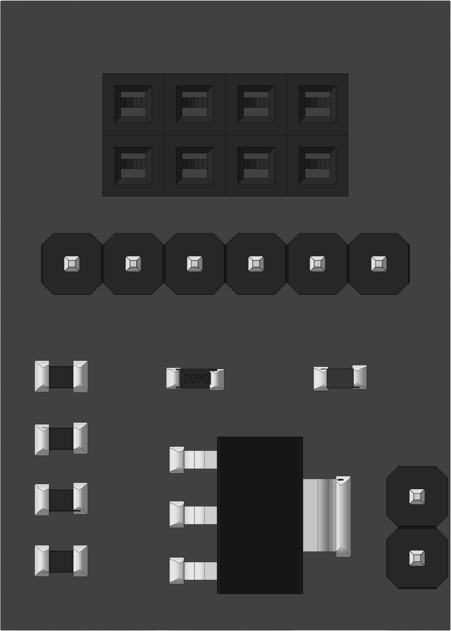
 Design with NRF24L01 5V Adapter in Cirkit Designer
Introduction
The NRF24L01 5V Adapter is a power supply module specifically designed to provide a stable 5V output for the NRF24L01 wireless transceiver module. This adapter ensures reliable operation by regulating the power supply, which is critical for maintaining consistent communication in wireless applications. It is particularly useful when the NRF24L01 module is used with microcontrollers that cannot directly supply the required power.
Explore Projects Built with NRF24L01 5V Adapter
 Open Project in Cirkit Designer
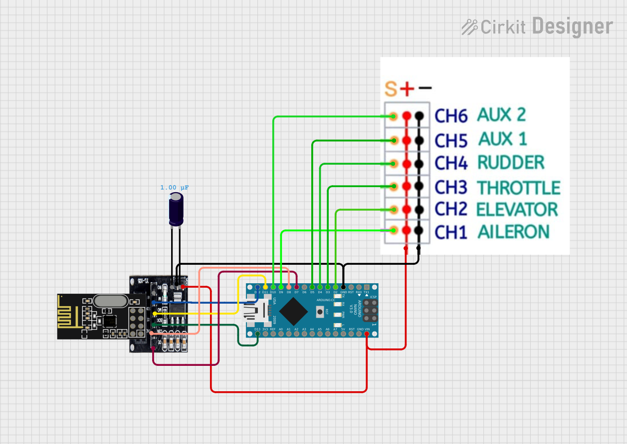 Open Project in Cirkit Designer
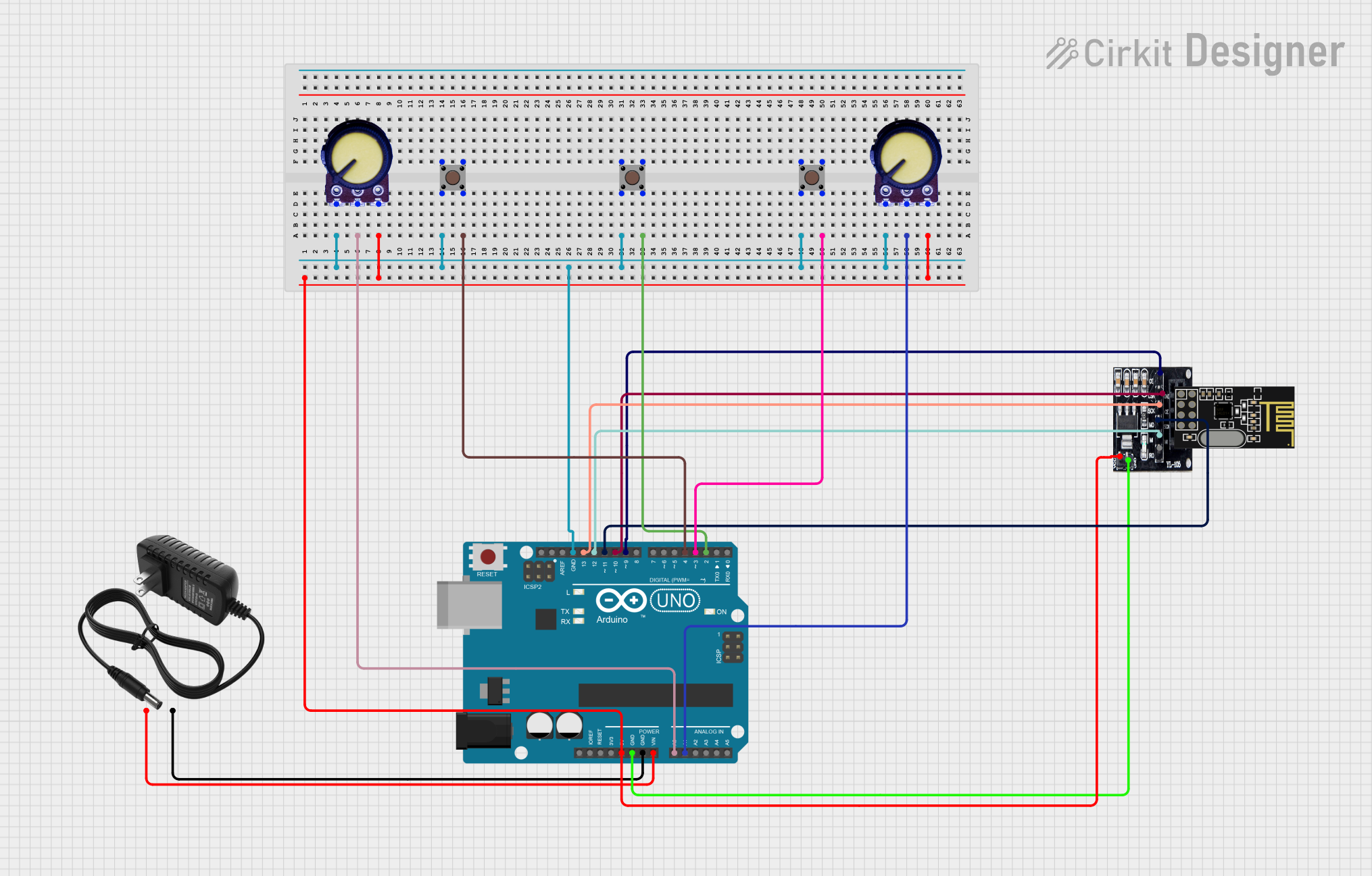 Open Project in Cirkit Designer
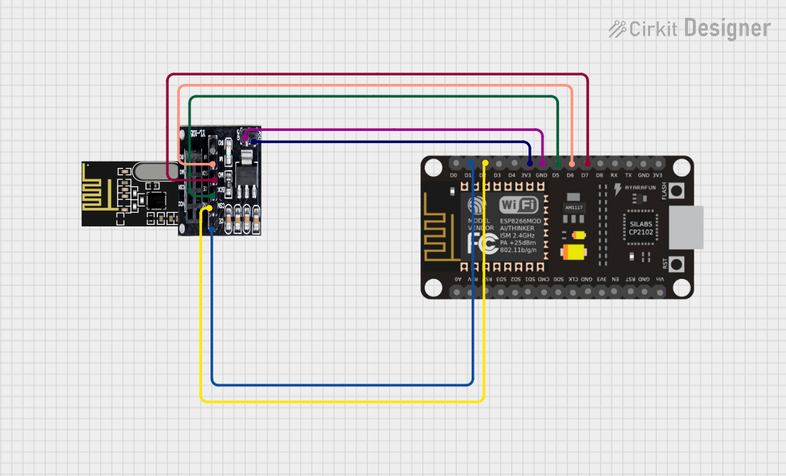 Open Project in Cirkit Designer
Explore Projects Built with NRF24L01 5V Adapter
Open Project in Cirkit DesignerOpen Project in Cirkit DesignerOpen Project in Cirkit DesignerOpen Project in Cirkit DesignerCommon Applications and Use Cases
- Wireless communication in IoT projects
- Remote control systems
- Home automation
- Sensor networks
- Robotics and drones
Technical Specifications
The NRF24L01 5V Adapter is designed to simplify the integration of the NRF24L01 module into your projects by providing a stable power source. Below are the key technical details:
Key Specifications
| Parameter | Value |
|---|---|
| Input Voltage | 5V DC |
| Output Voltage | 3.3V DC |
| Maximum Output Current | 200mA |
| Dimensions | 25mm x 18mm |
| Operating Temperature | -40°C to +85°C |
Pin Configuration and Descriptions
The NRF24L01 5V Adapter has a simple pinout for easy connection to the NRF24L01 module and the power source.
| Pin Name | Description |
|---|---|
| VCC | Connect to a 5V DC power source (e.g., Arduino 5V pin or external supply). |
| GND | Ground connection. |
| CE | Chip Enable pin for the NRF24L01 module. |
| CSN | Chip Select Not pin for SPI communication. |
| SCK | Serial Clock pin for SPI communication. |
| MOSI | Master Out Slave In pin for SPI communication. |
| MISO | Master In Slave Out pin for SPI communication. |
Usage Instructions
How to Use the NRF24L01 5V Adapter in a Circuit
Connect the Adapter to Power:
- Connect the
VCCpin of the adapter to a 5V DC power source. - Connect the
GNDpin of the adapter to the ground of your circuit.
- Connect the
Attach the NRF24L01 Module:
- Plug the NRF24L01 module directly into the adapter's header pins. Ensure proper alignment of the pins.
Connect to a Microcontroller:
- Use jumper wires to connect the adapter's SPI pins (
CE,CSN,SCK,MOSI,MISO) to the corresponding SPI pins on your microcontroller (e.g., Arduino UNO).
- Use jumper wires to connect the adapter's SPI pins (
Power On the Circuit:
- Once all connections are secure, power on the circuit. The adapter will regulate the 5V input to a stable 3.3V output for the NRF24L01 module.
Important Considerations and Best Practices
- Power Supply Stability: Ensure that the 5V power source is stable and capable of supplying sufficient current (at least 200mA) to avoid communication issues.
- Avoid Overheating: Do not exceed the maximum input voltage of 5V to prevent damage to the adapter.
- Proper Grounding: Ensure all ground connections in the circuit are properly connected to avoid noise and communication errors.
- Use Decoupling Capacitors: If you experience instability, consider adding a 10µF capacitor across the
VCCandGNDpins of the adapter.
Example Code for Arduino UNO
Below is an example of how to use the NRF24L01 module with the 5V adapter and an Arduino UNO for basic wireless communication.
#include <SPI.h>
#include <nRF24L01.h>
#include <RF24.h>

// Define the CE and CSN pins for the NRF24L01 module
#define CE_PIN 9
#define CSN_PIN 10

// Create an RF24 object
RF24 radio(CE_PIN, CSN_PIN);

// Define the address for communication
const byte address[6] = "00001";

void setup() {
  Serial.begin(9600); // Initialize serial communication
  radio.begin();      // Initialize the NRF24L01 module
  radio.openWritingPipe(address); // Set the address for transmission
  radio.setPALevel(RF24_PA_LOW);  // Set power amplifier level
  radio.stopListening();          // Set the module to transmit mode
}

void loop() {
  const char text[] = "Hello, World!"; // Message to send
  bool success = radio.write(&text, sizeof(text)); // Send the message

  if (success) {
    Serial.println("Message sent successfully!");
  } else {
    Serial.println("Message failed to send.");
  }

  delay(1000); // Wait 1 second before sending the next message
}
Troubleshooting and FAQs
Common Issues and Solutions
Issue: The NRF24L01 module is not communicating.
- Solution: Ensure the adapter is receiving a stable 5V input and that all connections are secure. Verify the SPI pin connections between the adapter and the microcontroller.
Issue: The module overheats during operation.
- Solution: Check that the input voltage does not exceed 5V. Ensure the NRF24L01 module is properly seated in the adapter.
Issue: Unstable communication or frequent packet loss.
- Solution: Add a decoupling capacitor (e.g., 10µF) across the
VCCandGNDpins of the adapter. Ensure the power source can supply sufficient current.
- Solution: Add a decoupling capacitor (e.g., 10µF) across the
Issue: The Arduino code does not work.
- Solution: Verify that the CE and CSN pins in the code match the actual connections. Ensure the
RF24library is installed in your Arduino IDE.
- Solution: Verify that the CE and CSN pins in the code match the actual connections. Ensure the
FAQs
Can I use a power source higher than 5V? No, the adapter is designed for a maximum input voltage of 5V. Using a higher voltage may damage the adapter and the NRF24L01 module.
Do I need additional components to use this adapter? In most cases, no additional components are required. However, adding a decoupling capacitor can improve stability in noisy environments.
Is this adapter compatible with other 3.3V modules? While it is designed for the NRF24L01, it can be used with other 3.3V modules as long as the current requirements do not exceed 200mA.