Cirkit Designer Logo
Cirkit Designer
Your all-in-one circuit design IDE
Home / 
Component Documentation

How to Use ebyte e220-400t22d: Examples, Pinouts, and Specs

Image of ebyte e220-400t22d
Cirkit Designer LogoDesign with ebyte e220-400t22d in Cirkit Designer

Introduction

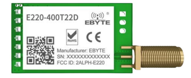
The Ebyte E220-400T22D is a low-power, long-range wireless transceiver module that operates in the 400 MHz frequency band. It is designed for applications requiring reliable data transmission over distances up to several kilometers. This module is ideal for IoT systems, remote monitoring, industrial automation, and smart agriculture, where robust and efficient communication is essential.

Explore Projects Built with ebyte e220-400t22d

Use Cirkit Designer to design, explore, and prototype these projects online. Some projects support real-time simulation. Click "Open Project" to start designing instantly!
Satellite-Based Timing and Navigation System with SDR and Atomic Clock Synchronization
Image of GPS 시스템 측정 구성도_Confirm: A project utilizing ebyte e220-400t22d in a practical application
This circuit appears to be a complex system involving power supply management, GPS and timing synchronization, and data communication. It includes a SI-TEX G1 Satellite Compass for GPS data, an XHTF1021 Atomic Rubidium Clock for precise timing, and Ettus USRP B200 units for software-defined radio communication. Power is supplied through various SMPS units and distributed via terminal blocks and DC jacks. Data communication is facilitated by Beelink MINI S12 N95 computers, RS232 splitters, and a 1000BASE-T Media Converter for network connectivity. RF Directional Couplers are used to interface antennas with the USRP units, and the entire system is likely contained within cases for protection and organization.
Cirkit Designer LogoOpen Project in Cirkit Designer
ESP32C3 and SIM800L Powered Smart Energy Monitor with OLED Display and Wi-Fi Connectivity
Image of SERVER: A project utilizing ebyte e220-400t22d in a practical application
This circuit is a power monitoring system that uses an ESP32C3 microcontroller to collect power usage data from slave devices via WiFi and SMS. The collected data is displayed on a 0.96" OLED screen, and the system is powered by an AC-DC converter module. Additionally, the circuit includes a SIM800L GSM module for SMS communication and LEDs for status indication.
Cirkit Designer LogoOpen Project in Cirkit Designer
Battery-Powered Arduino Nano Weather Station with LoRa Communication
Image of Aduino LoRa Transmitter: A project utilizing ebyte e220-400t22d in a practical application
This circuit is a wireless sensor system that uses an Arduino Nano to collect data from a DHT22 temperature and humidity sensor and an ACS712 current sensor. The data is transmitted via an EBYTE LoRa E220 module, and the system is powered by a 18650 battery with a TP4056 charging module and a step-up boost converter to ensure a stable 5V supply.
Cirkit Designer LogoOpen Project in Cirkit Designer
Transistor-Based LED Control Circuit with Capacitors and Resistors
Image of FLIP-FLOP CKT.: A project utilizing ebyte e220-400t22d in a practical application
This circuit is a dual-transistor LED driver with two NPN transistors controlling two LEDs (one red and one blue). The transistors are configured to switch the LEDs on and off, with resistors and capacitors used for biasing and stabilization.
Cirkit Designer LogoOpen Project in Cirkit Designer

Explore Projects Built with ebyte e220-400t22d

Use Cirkit Designer to design, explore, and prototype these projects online. Some projects support real-time simulation. Click "Open Project" to start designing instantly!
Image of GPS 시스템 측정 구성도_Confirm: A project utilizing ebyte e220-400t22d in a practical application
Satellite-Based Timing and Navigation System with SDR and Atomic Clock Synchronization
This circuit appears to be a complex system involving power supply management, GPS and timing synchronization, and data communication. It includes a SI-TEX G1 Satellite Compass for GPS data, an XHTF1021 Atomic Rubidium Clock for precise timing, and Ettus USRP B200 units for software-defined radio communication. Power is supplied through various SMPS units and distributed via terminal blocks and DC jacks. Data communication is facilitated by Beelink MINI S12 N95 computers, RS232 splitters, and a 1000BASE-T Media Converter for network connectivity. RF Directional Couplers are used to interface antennas with the USRP units, and the entire system is likely contained within cases for protection and organization.
Cirkit Designer LogoOpen Project in Cirkit Designer
Image of SERVER: A project utilizing ebyte e220-400t22d in a practical application
ESP32C3 and SIM800L Powered Smart Energy Monitor with OLED Display and Wi-Fi Connectivity
This circuit is a power monitoring system that uses an ESP32C3 microcontroller to collect power usage data from slave devices via WiFi and SMS. The collected data is displayed on a 0.96" OLED screen, and the system is powered by an AC-DC converter module. Additionally, the circuit includes a SIM800L GSM module for SMS communication and LEDs for status indication.
Cirkit Designer LogoOpen Project in Cirkit Designer
Image of Aduino LoRa Transmitter: A project utilizing ebyte e220-400t22d in a practical application
Battery-Powered Arduino Nano Weather Station with LoRa Communication
This circuit is a wireless sensor system that uses an Arduino Nano to collect data from a DHT22 temperature and humidity sensor and an ACS712 current sensor. The data is transmitted via an EBYTE LoRa E220 module, and the system is powered by a 18650 battery with a TP4056 charging module and a step-up boost converter to ensure a stable 5V supply.
Cirkit Designer LogoOpen Project in Cirkit Designer
Image of FLIP-FLOP CKT.: A project utilizing ebyte e220-400t22d in a practical application
Transistor-Based LED Control Circuit with Capacitors and Resistors
This circuit is a dual-transistor LED driver with two NPN transistors controlling two LEDs (one red and one blue). The transistors are configured to switch the LEDs on and off, with resistors and capacitors used for biasing and stabilization.
Cirkit Designer LogoOpen Project in Cirkit Designer

Common Applications

  • Internet of Things (IoT) networks
  • Remote monitoring and control systems
  • Smart agriculture and environmental monitoring
  • Industrial automation and telemetry
  • Wireless sensor networks

Technical Specifications

Key Technical Details

Parameter Value
Frequency Range 410 MHz – 441 MHz
Modulation Method LoRa
Transmission Power Up to 22 dBm (160 mW)
Communication Distance Up to 5 km (line of sight)
Operating Voltage 2.8 V – 5.5 V
Operating Current 120 mA (transmitting at max power)
Sleep Current < 5 µA
Interface UART (TTL)
Baud Rate 1200 bps – 115200 bps
Operating Temperature -40°C to +85°C
Dimensions 24 mm × 43 mm × 3 mm

Pin Configuration and Descriptions

Pin Number Pin Name Description
1 M0 Mode selection pin (used to configure the module's operating mode)
2 M1 Mode selection pin (used to configure the module's operating mode)
3 RXD UART data input (connect to the TX pin of the microcontroller)
4 TXD UART data output (connect to the RX pin of the microcontroller)
5 AUX Auxiliary pin (indicates module status, e.g., busy or idle)
6 VCC Power supply input (2.8 V – 5.5 V)
7 GND Ground

Usage Instructions

How to Use the E220-400T22D in a Circuit

  1. Power Supply: Connect the VCC pin to a stable power source (2.8 V – 5.5 V) and the GND pin to ground.
  2. UART Communication: Connect the RXD pin to the TX pin of your microcontroller and the TXD pin to the RX pin of your microcontroller.
  3. Mode Selection: Use the M0 and M1 pins to configure the module's operating mode:
    • Mode 0 (Normal Mode): M0 = 0, M1 = 0
    • Mode 1 (Wake-up Mode): M0 = 1, M1 = 0
    • Mode 2 (Power-saving Mode): M0 = 0, M1 = 1
    • Mode 3 (Configuration Mode): M0 = 1, M1 = 1
  4. AUX Pin: Monitor the AUX pin to check the module's status. For example, when the AUX pin is high, the module is idle or ready to transmit/receive data.

Important Considerations

  • Use a proper antenna to ensure optimal communication range and signal quality.
  • Avoid placing the module near sources of electromagnetic interference (EMI).
  • Ensure the UART baud rate of the microcontroller matches the module's configured baud rate.
  • Use decoupling capacitors near the VCC pin to stabilize the power supply.

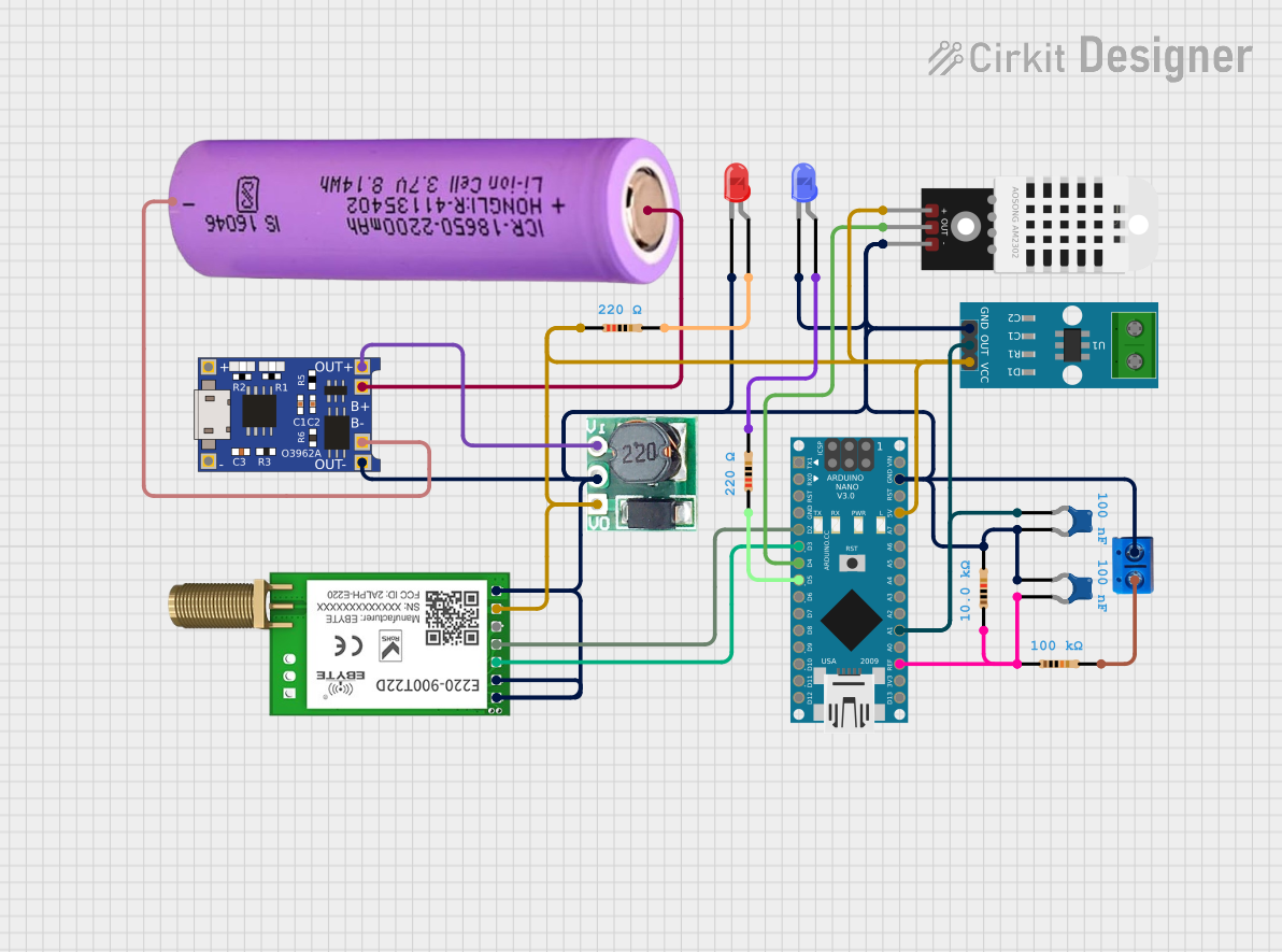
Example: Connecting to an Arduino UNO

Below is an example of how to connect the E220-400T22D to an Arduino UNO and send data.

Wiring Diagram

E220-400T22D Pin Arduino UNO Pin
VCC 5V
GND GND
RXD D3 (via voltage divider if using 5V logic)
TXD D2
M0 D4
M1 D5
AUX D6

Arduino Code Example

#include <SoftwareSerial.h>

// Define pins for SoftwareSerial
#define E220_RX 2  // Arduino pin connected to E220 TXD
#define E220_TX 3  // Arduino pin connected to E220 RXD
#define M0 4       // Mode selection pin M0
#define M1 5       // Mode selection pin M1
#define AUX 6      // Auxiliary pin

SoftwareSerial e220Serial(E220_RX, E220_TX);

void setup() {
  // Initialize serial communication
  Serial.begin(9600);  // For debugging
  e220Serial.begin(9600);  // Communication with E220 module

  // Configure mode selection pins
  pinMode(M0, OUTPUT);
  pinMode(M1, OUTPUT);
  pinMode(AUX, INPUT);

  // Set module to Normal Mode (M0 = 0, M1 = 0)
  digitalWrite(M0, LOW);
  digitalWrite(M1, LOW);

  Serial.println("E220-400T22D Initialized");
}

void loop() {
  // Send data to the E220 module
  e220Serial.println("Hello, E220!");

  // Wait for the module to process the data
  delay(1000);

  // Check if data is received
  if (e220Serial.available()) {
    String receivedData = e220Serial.readString();
    Serial.print("Received: ");
    Serial.println(receivedData);
  }

  delay(2000);  // Delay between transmissions
}

Troubleshooting and FAQs

Common Issues

  1. No Communication Between Module and Microcontroller

    • Ensure the UART baud rate matches between the module and the microcontroller.
    • Verify the wiring connections, especially RXD and TXD.
  2. Poor Communication Range

    • Check the antenna connection and ensure it is properly installed.
    • Avoid obstacles or interference in the communication path.
  3. Module Not Responding

    • Verify the power supply voltage is within the specified range (2.8 V – 5.5 V).
    • Check the AUX pin to ensure the module is not busy.

FAQs

Q: Can I use the E220-400T22D with a 3.3V microcontroller?
A: Yes, the module supports a wide operating voltage range (2.8 V – 5.5 V). Ensure proper logic level matching for UART communication.

Q: How do I configure the module's parameters (e.g., baud rate, channel)?
A: Set the module to Configuration Mode (M0 = 1, M1 = 1) and use AT commands via UART to configure parameters.

Q: What is the maximum communication distance?
A: The module can achieve up to 5 km in line-of-sight conditions with a proper antenna and minimal interference.

Q: Can I use multiple E220 modules in the same network?
A: Yes, you can configure multiple modules to operate on the same channel and address for communication.