How to Use MINI DC 5V 2.4A CHARGE/DISCHARGE MODULE: Examples, Pinouts, and Specs
Introduction
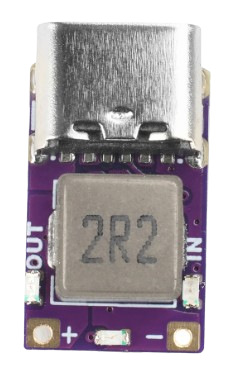
The MINI DC 5V 2.4A CHARGE/DISCHARGE MODULE is a compact and versatile electronic component designed for charging and discharging applications. It operates at a voltage of 5V and can handle a current of up to 2.4A, making it ideal for powering small devices, charging batteries, or integrating into portable power systems. Its small form factor and efficient design make it suitable for a wide range of applications, including DIY electronics projects, power banks, and embedded systems.
Explore Projects Built with MINI DC 5V 2.4A CHARGE/DISCHARGE MODULE


Explore Projects Built with MINI DC 5V 2.4A CHARGE/DISCHARGE MODULE
Common Applications and Use Cases
- Charging lithium-ion or lithium-polymer batteries.
- Powering small electronic devices such as microcontrollers, sensors, or LEDs.
- Integrating into portable power systems or power banks.
- Providing stable 5V output for embedded systems or IoT devices.
Technical Specifications
Below are the key technical details and pin configuration for the MINI DC 5V 2.4A CHARGE/DISCHARGE MODULE:
Key Technical Details
| Parameter | Value |
|---|---|
| Input Voltage | 5V DC |
| Output Voltage | 5V DC |
| Maximum Output Current | 2.4A |
| Efficiency | Up to 92% |
| Dimensions | Compact (varies by supplier) |
| Operating Temperature | -20°C to +60°C |
| Protection Features | Overcurrent, Overvoltage, |
| Short Circuit Protection |
Pin Configuration and Descriptions
| Pin Name | Description |
|---|---|
| VIN | Input voltage pin (5V DC). Connect to a 5V power source. |
| GND | Ground pin. Connect to the ground of the power source and the load. |
| VOUT | Output voltage pin (5V DC). Connect to the load or device to be powered. |
| CHG | Charging indicator pin. Outputs a signal when charging is active. |
| DISCHG | Discharging indicator pin. Outputs a signal when discharging is active. |
Usage Instructions
How to Use the Component in a Circuit
- Power Input: Connect a stable 5V DC power source to the
VINpin and the ground of the power source to theGNDpin. - Load Connection: Connect the device or load to the
VOUTpin and its ground to theGNDpin. - Charging Applications: For charging batteries, ensure the battery's voltage and current ratings are compatible with the module's specifications.
- Indicator Pins: Use the
CHGandDISCHGpins to monitor the charging and discharging status. These pins can be connected to LEDs or a microcontroller for status indication.
Important Considerations and Best Practices
- Ensure the input voltage is stable and does not exceed 5V to avoid damaging the module.
- Do not exceed the maximum output current of 2.4A to prevent overheating or triggering the overcurrent protection.
- Use proper heat dissipation methods if the module operates at high currents for extended periods.
- For battery charging, verify that the battery has built-in protection circuitry or use an external protection circuit.
Example: Connecting to an Arduino UNO
The module can be used to power an Arduino UNO or monitor its charging/discharging status. Below is an example of how to connect the module to an Arduino UNO and read the status pins:
Circuit Connections
- Connect the
VINpin of the module to a 5V power source. - Connect the
GNDpin of the module to the Arduino's GND. - Connect the
VOUTpin of the module to the Arduino's 5V pin. - Connect the
CHGpin to Arduino digital pin 2. - Connect the
DISCHGpin to Arduino digital pin 3.
Arduino Code Example
// Define pins for CHG and DISCHG
const int chgPin = 2;  // Pin connected to CHG (charging indicator)
const int dischgPin = 3;  // Pin connected to DISCHG (discharging indicator)

void setup() {
  // Initialize serial communication for debugging
  Serial.begin(9600);

  // Set CHG and DISCHG pins as input
  pinMode(chgPin, INPUT);
  pinMode(dischgPin, INPUT);
}

void loop() {
  // Read the status of CHG and DISCHG pins
  int chgStatus = digitalRead(chgPin);
  int dischgStatus = digitalRead(dischgPin);

  // Print the status to the Serial Monitor
  if (chgStatus == HIGH) {
    Serial.println("Charging in progress...");
  } else {
    Serial.println("Not charging.");
  }

  if (dischgStatus == HIGH) {
    Serial.println("Discharging in progress...");
  } else {
    Serial.println("Not discharging.");
  }

  // Add a small delay to avoid flooding the Serial Monitor
  delay(500);
}
Troubleshooting and FAQs
Common Issues and Solutions
Module Overheating
- Cause: Exceeding the maximum current rating of 2.4A.
- Solution: Reduce the load current or improve heat dissipation using a heatsink or fan.
No Output Voltage
- Cause: Incorrect wiring or insufficient input voltage.
- Solution: Verify the connections and ensure the input voltage is stable at 5V.
Charging/Discharging Indicators Not Working
- Cause: Faulty connections to the
CHGorDISCHGpins. - Solution: Check the connections and ensure the pins are properly connected to the monitoring circuit.
- Cause: Faulty connections to the
Device Not Charging
- Cause: Incompatible battery or insufficient input power.
- Solution: Verify the battery's specifications and ensure the input power source can supply sufficient current.
FAQs
Q: Can this module charge a 3.7V lithium-ion battery?
A: Yes, but you must ensure the battery has built-in protection circuitry or use an external charging controller to regulate the voltage and current.
Q: Can I use this module with a 12V power source?
A: No, the module is designed for a 5V input only. Using a higher voltage may damage the module.
Q: Is the module suitable for powering a Raspberry Pi?
A: Yes, as long as the total current draw of the Raspberry Pi and connected peripherals does not exceed 2.4A.
Q: Does the module have reverse polarity protection?
A: This depends on the specific design of the module. Check with the supplier or test carefully before use.