How to Use Usb C breakout board: Examples, Pinouts, and Specs
Introduction
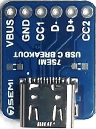
The USB-C Breakout Board by SmartElex (Part ID: R177461) is a compact and versatile component designed to simplify the integration of USB Type-C connectors into various electronic projects. This breakout board provides easy access to the pins of a USB Type-C connector, making it ideal for prototyping, testing, and development purposes. Whether you're working on a custom USB device, power delivery system, or data communication project, this breakout board offers a convenient solution.
Explore Projects Built with Usb C breakout board


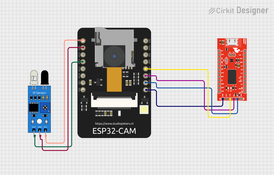
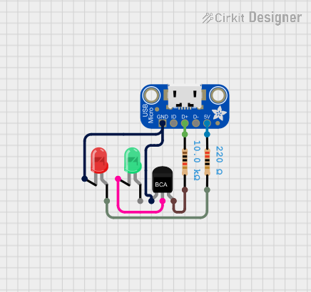
Explore Projects Built with Usb C breakout board
Common Applications and Use Cases
- Prototyping and Development: Quickly test and develop USB-C based circuits.
- Custom USB Devices: Create custom USB peripherals and accessories.
- Power Delivery Systems: Implement USB-C power delivery in your projects.
- Data Communication: Facilitate data transfer between devices using USB-C.
Technical Specifications
Key Technical Details
| Specification | Value |
|---|---|
| Manufacturer | SmartElex |
| Part ID | R177461 |
| Connector Type | USB Type-C |
| Voltage Rating | 5V (Standard USB Power) |
| Current Rating | Up to 3A |
| Dimensions | 20mm x 15mm |
| Mounting Type | Through-hole |
| PCB Material | FR4 |
Pin Configuration and Descriptions
| Pin Number | Pin Name | Description |
|---|---|---|
| 1 | GND | Ground |
| 2 | VBUS | Power Supply (5V) |
| 3 | CC1 | Configuration Channel 1 |
| 4 | D+ | USB 2.0 Data Positive |
| 5 | D- | USB 2.0 Data Negative |
| 6 | CC2 | Configuration Channel 2 |
| 7 | SBU1 | Sideband Use 1 |
| 8 | SBU2 | Sideband Use 2 |
| 9 | VCONN | Power for Active Cable (Optional, 5V) |
| 10 | GND | Ground |
Usage Instructions
How to Use the Component in a Circuit
Power Supply:
- Connect the VBUS pin to a 5V power source.
- Connect the GND pin to the ground of your circuit.
Data Communication:
- Connect the D+ and D- pins to the corresponding data lines of your USB device or microcontroller.
Configuration Channels:
- Use the CC1 and CC2 pins for USB-C configuration and power delivery negotiation.
Optional Connections:
- SBU1 and SBU2 can be used for alternate modes or sideband communication.
- VCONN can be connected if your application requires power for an active cable.
Important Considerations and Best Practices
- Voltage Levels: Ensure that the voltage levels on the VBUS and VCONN pins do not exceed 5V to prevent damage to the breakout board and connected devices.
- Current Rating: The breakout board can handle up to 3A of current. Ensure that your power source and connected devices do not exceed this limit.
- Proper Grounding: Always connect the GND pins to a common ground to ensure proper operation and avoid potential issues with data communication and power delivery.
Example Code for Arduino UNO
Here is an example of how to use the USB-C Breakout Board with an Arduino UNO for basic data communication:
// Example code to read data from a USB-C device using Arduino UNO

#include <SoftwareSerial.h>

// Define the pins for SoftwareSerial
const int rxPin = 2; // RX pin of Arduino
const int txPin = 3; // TX pin of Arduino

// Create a SoftwareSerial object
SoftwareSerial usbSerial(rxPin, txPin);

void setup() {
  // Initialize the serial communication
  Serial.begin(9600);
  usbSerial.begin(9600);

  // Print a message to the serial monitor
  Serial.println("USB-C Breakout Board Example");
}

void loop() {
  // Check if data is available from the USB-C device
  if (usbSerial.available()) {
    // Read the data and print it to the serial monitor
    char data = usbSerial.read();
    Serial.print("Data received: ");
    Serial.println(data);
  }

  // Add a small delay to avoid overwhelming the serial monitor
  delay(100);
}
Troubleshooting and FAQs
Common Issues Users Might Face
No Power or Data Communication:
- Solution: Check the connections to ensure that the VBUS and GND pins are properly connected to the power source and ground. Verify that the D+ and D- pins are correctly connected to the data lines.
Overheating:
- Solution: Ensure that the current drawn by the connected devices does not exceed the 3A rating of the breakout board. Use appropriate heat dissipation methods if necessary.
Unstable Data Transfer:
- Solution: Verify that the GND connections are secure and that there is no electrical noise or interference affecting the data lines. Use shielded cables if needed.
Solutions and Tips for Troubleshooting
- Double-check Connections: Ensure that all connections are secure and correctly wired according to the pin configuration table.
- Use Proper Power Supply: Make sure that the power supply provides a stable 5V output and can handle the current requirements of your project.
- Monitor Serial Output: Use the serial monitor to debug and verify data communication between the USB-C device and the Arduino UNO.
By following this documentation, you should be able to effectively integrate the SmartElex USB-C Breakout Board (Part ID: R177461) into your projects and troubleshoot any common issues that may arise. Happy prototyping!