How to Use 12V to 5V: Examples, Pinouts, and Specs
Introduction
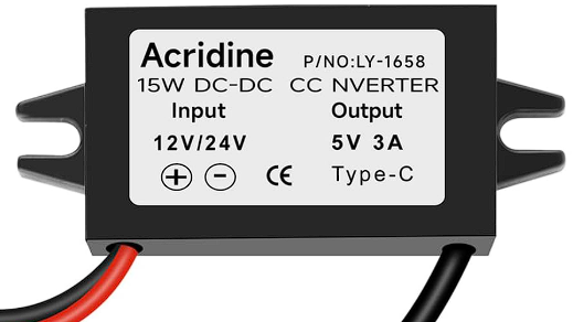
The 12V to 5V voltage regulator is an essential electronic component designed to step down a 12V input voltage to a stable 5V output. This regulator is widely used in applications where 5V devices, such as microcontrollers, sensors, and USB-powered peripherals, need to be powered from a higher voltage source like a car battery or a 12V power supply. Its compact design and reliable performance make it a popular choice for embedded systems, automotive electronics, and DIY projects.
Explore Projects Built with 12V to 5V


Explore Projects Built with 12V to 5V
Common Applications
- Powering 5V microcontrollers (e.g., Arduino, Raspberry Pi)
- USB device power supplies
- Automotive electronics (e.g., powering GPS modules, dash cams)
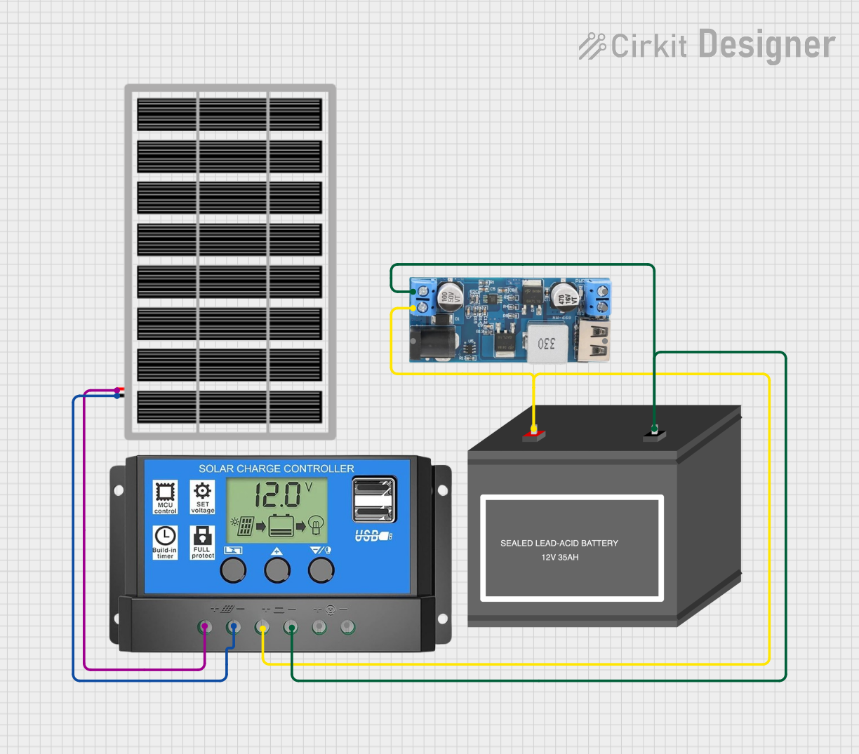
- Battery-powered systems requiring voltage regulation
- General-purpose voltage step-down circuits
Technical Specifications
The following table outlines the key technical details of the 12V to 5V voltage regulator:
| Parameter | Value |
|---|---|
| Input Voltage Range | 7V to 24V |
| Output Voltage | 5V ± 0.1V |
| Maximum Output Current | 2A (varies by model) |
| Efficiency | Up to 90% (depending on load) |
| Operating Temperature | -40°C to +85°C |
| Protection Features | Overcurrent, Overtemperature, |
| and Short-Circuit Protection |
Pin Configuration
The pinout of the 12V to 5V voltage regulator module is as follows:
| Pin Name | Description |
|---|---|
| VIN | Input voltage pin (connect to 12V source) |
| GND | Ground pin (common ground for input/output) |
| VOUT | Regulated 5V output pin |
Usage Instructions
How to Use the Component in a Circuit
Connect the Input Voltage (VIN):
Attach the VIN pin to a 12V DC power source. Ensure the input voltage is within the specified range (7V to 24V) to avoid damaging the regulator.Connect the Ground (GND):
Connect the GND pin to the ground of your circuit. This serves as the common reference point for both input and output.Connect the Output Voltage (VOUT):
Attach the VOUT pin to the 5V device or circuit you wish to power. Ensure the connected load does not exceed the maximum output current rating (2A).Optional Capacitors:
For improved stability, you can add a 10µF capacitor across the input (VIN and GND) and a 22µF capacitor across the output (VOUT and GND). These capacitors help reduce voltage ripple and noise.
Important Considerations
Heat Dissipation:
If the regulator is operating near its maximum current rating, it may generate heat. Use a heatsink or ensure proper ventilation to prevent overheating.Input Voltage Range:
Always ensure the input voltage is within the specified range. Exceeding the maximum input voltage can permanently damage the regulator.Load Current:
Do not exceed the maximum output current rating. Overloading the regulator may trigger protection features or cause it to fail.
Example: Using with an Arduino UNO
The 12V to 5V regulator can be used to power an Arduino UNO from a 12V source. Below is an example circuit and Arduino code:
Circuit Connections
- Connect the VIN pin of the regulator to a 12V DC power source.
- Connect the GND pin of the regulator to the ground of the power source and the Arduino.
- Connect the VOUT pin of the regulator to the 5V pin of the Arduino UNO.
Arduino Code Example
// Example code to blink an LED connected to pin 13 of the Arduino UNO
// Ensure the Arduino is powered via the 12V to 5V regulator

void setup() {
  pinMode(13, OUTPUT); // Set pin 13 as an output
}

void loop() {
  digitalWrite(13, HIGH); // Turn the LED on
  delay(1000);            // Wait for 1 second
  digitalWrite(13, LOW);  // Turn the LED off
  delay(1000);            // Wait for 1 second
}
Troubleshooting and FAQs
Common Issues and Solutions
No Output Voltage:
- Cause: Input voltage is too low or not connected properly.
- Solution: Verify that the input voltage is within the specified range (7V to 24V) and that all connections are secure.
Overheating:
- Cause: Excessive load current or poor ventilation.
- Solution: Reduce the load current or add a heatsink to the regulator.
Voltage Drop Under Load:
- Cause: Insufficient input voltage or inadequate wiring.
- Solution: Ensure the input voltage is stable and use thicker wires to reduce resistance.
Regulator Shuts Down:
- Cause: Overcurrent or short-circuit protection triggered.
- Solution: Check for short circuits in the output and ensure the load does not exceed the maximum current rating.
FAQs
Q: Can I use this regulator to power a Raspberry Pi?
A: Yes, but ensure the regulator can supply sufficient current (at least 2A) for the Raspberry Pi model you are using.
Q: Can I use this regulator with a 24V input?
A: Yes, as long as the input voltage does not exceed the maximum rating (24V) and the regulator's efficiency is sufficient for your application.
Q: Do I need external capacitors?
A: While not mandatory, adding capacitors (10µF on the input and 22µF on the output) can improve stability and reduce noise.
Q: Is this regulator suitable for automotive use?
A: Yes, it is commonly used in automotive applications to power 5V devices from a 12V car battery. However, ensure the regulator has adequate protection against voltage spikes.