
How to Use VFD: Examples, Pinouts, and Specs
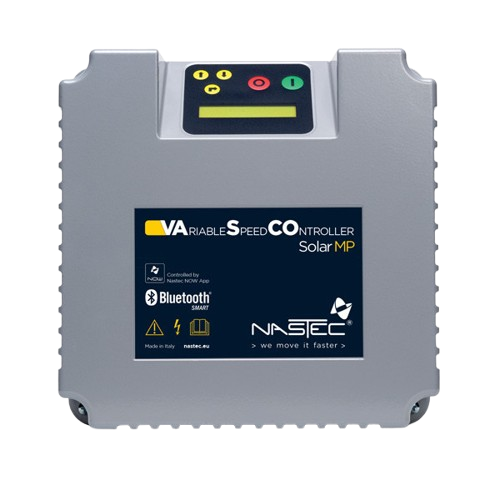
 Design with VFD in Cirkit Designer
Introduction
A Variable Frequency Drive (VFD), such as the Nastec 3P VFD, is an electronic device designed to control the speed and torque of an electric motor. It achieves this by varying the frequency and voltage of the power supplied to the motor. VFDs are widely used in industrial and commercial applications to improve energy efficiency, enhance motor control, and extend the lifespan of motors.
Explore Projects Built with VFD
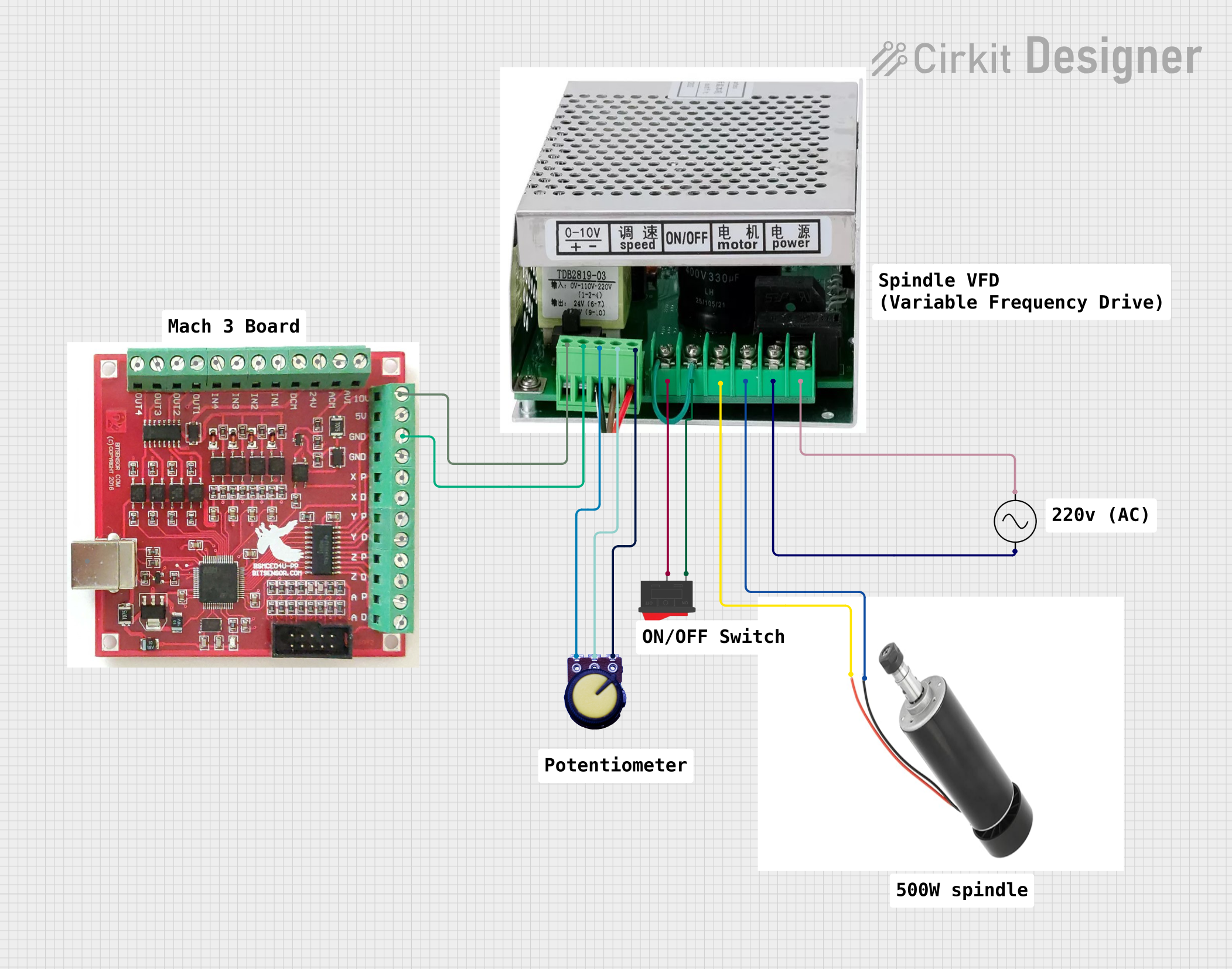 Open Project in Cirkit Designer
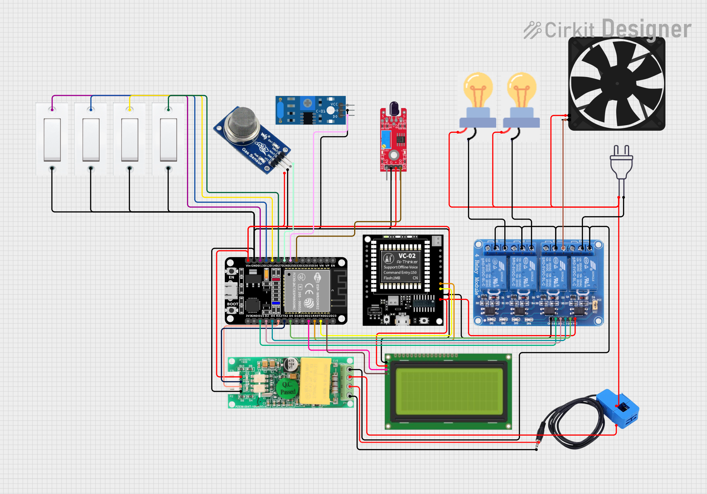 Open Project in Cirkit Designer
 Open Project in Cirkit Designer
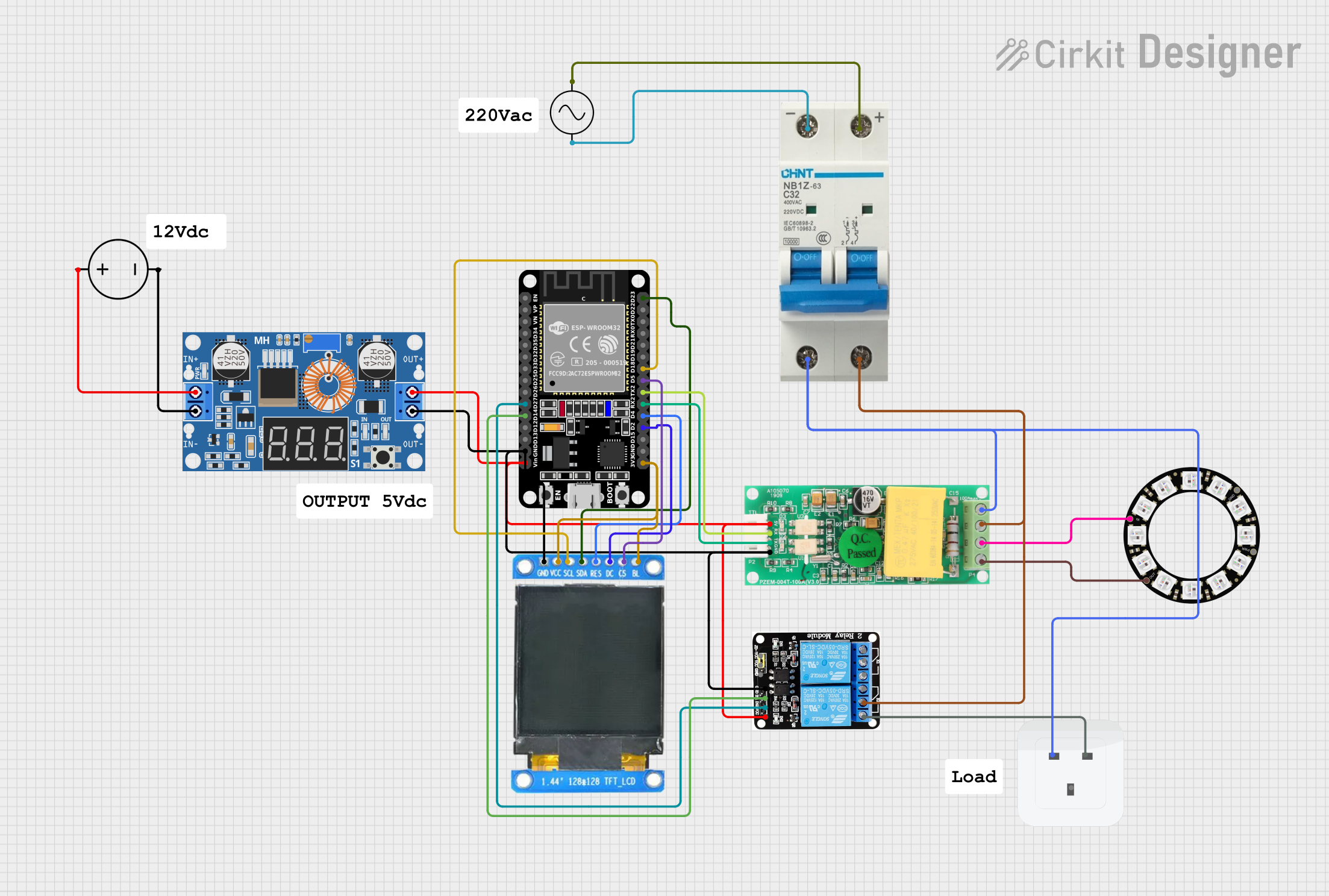 Open Project in Cirkit Designer
Explore Projects Built with VFD
Open Project in Cirkit DesignerOpen Project in Cirkit DesignerOpen Project in Cirkit DesignerOpen Project in Cirkit DesignerCommon Applications and Use Cases
- HVAC Systems: Controlling fans, pumps, and compressors for energy-efficient operation.
- Industrial Automation: Managing conveyor belts, mixers, and other motor-driven machinery.
- Water and Wastewater Management: Regulating pump speeds to optimize flow and pressure.
- Renewable Energy Systems: Controlling motors in wind turbines and solar tracking systems.
- Agriculture: Operating irrigation pumps and grain handling equipment.
Technical Specifications
The Nastec 3P VFD is designed to provide precise motor control with robust performance. Below are its key technical specifications:
General Specifications
| Parameter | Value |
|---|---|
| Manufacturer | Nastec |
| Part ID | 3P VFD |
| Input Voltage Range | 200-240V AC (Single/Three-Phase) |
| Output Voltage Range | 0-240V AC |
| Frequency Range | 0-400 Hz |
| Power Rating | 0.75 kW to 22 kW (varies by model) |
| Control Method | V/F Control, Sensorless Vector Control |
| Efficiency | ≥ 98% |
| Operating Temperature | -10°C to 50°C |
| Protection Rating | IP20 (standard), optional IP55 |
| Communication Protocols | Modbus RTU, RS485 |
Pin Configuration and Descriptions
The Nastec 3P VFD features a terminal block for input/output connections. Below is the pin configuration:
Power Terminals
| Pin Label | Description |
|---|---|
| R/L1 | AC Input Phase 1 (Line) |
| S/L2 | AC Input Phase 2 (Line) |
| T/L3 | AC Input Phase 3 (Line) |
| U/T1 | Motor Output Phase 1 |
| V/T2 | Motor Output Phase 2 |
| W/T3 | Motor Output Phase 3 |
Control Terminals
| Pin Label | Description |
|---|---|
| +10V | 10V DC Output for Potentiometer |
| AI1 | Analog Input 1 (0-10V or 4-20mA) |
| DI1 | Digital Input 1 (Start/Stop) |
| DI2 | Digital Input 2 (Direction) |
| AO1 | Analog Output 1 (0-10V) |
| GND | Ground |
Usage Instructions
How to Use the Nastec 3P VFD in a Circuit
Wiring the VFD:
- Connect the AC power supply to the input terminals (R/L1, S/L2, T/L3).
- Connect the motor to the output terminals (U/T1, V/T2, W/T3).
- Ensure proper grounding to avoid electrical hazards.
Configuring the VFD:
- Use the built-in keypad or an external programming tool to set parameters such as motor voltage, frequency range, and control mode.
- For analog control, connect a potentiometer or a 4-20mA signal to the AI1 terminal.
Starting the Motor:
- Use the DI1 terminal for start/stop control. A simple push-button switch can be connected here.
- Adjust the speed using the potentiometer or the keypad.
Monitoring and Communication:
- Use the Modbus RTU protocol via the RS485 interface for remote monitoring and control.
Important Considerations and Best Practices
- Motor Compatibility: Ensure the motor's voltage and current ratings match the VFD's output specifications.
- Cooling: Install the VFD in a well-ventilated area to prevent overheating.
- EMI Shielding: Use shielded cables for motor connections to minimize electromagnetic interference.
- Parameter Settings: Double-check all parameter settings before starting the motor to avoid damage.
- Safety: Always disconnect power before performing any wiring or maintenance.
Example Code for Arduino UNO Integration
The Nastec 3P VFD can be controlled via Modbus RTU using an Arduino UNO. Below is an example code snippet:
#include <ModbusMaster.h>

// Create ModbusMaster object
ModbusMaster node;

void setup() {
  Serial.begin(9600); // Initialize serial communication
  node.begin(1, Serial); // Set Modbus slave ID to 1
}

void loop() {
  uint8_t result;

  // Write a frequency value (e.g., 50 Hz) to the VFD
  result = node.writeSingleRegister(0x2000, 50);
  // 0x2000 is the register address for frequency

  if (result == node.ku8MBSuccess) {
    Serial.println("Frequency set successfully!");
  } else {
    Serial.println("Failed to set frequency.");
  }

  delay(1000); // Wait for 1 second
}
Note: Replace 0x2000 with the appropriate register address based on the VFD's Modbus documentation.
Troubleshooting and FAQs
Common Issues and Solutions
Motor Does Not Start:
- Cause: Incorrect wiring or parameter settings.
- Solution: Verify all connections and ensure the start/stop command is properly configured.
Overheating:
- Cause: Poor ventilation or excessive load.
- Solution: Improve airflow around the VFD and reduce the motor load.
Communication Failure:
- Cause: Incorrect Modbus settings or wiring.
- Solution: Check the baud rate, slave ID, and RS485 connections.
Erratic Motor Speed:
- Cause: Noise on the analog input or incorrect parameter settings.
- Solution: Use shielded cables and review the VFD's configuration.
FAQs
Q: Can the Nastec 3P VFD be used with single-phase motors?
A: Yes, but ensure the motor is compatible with the VFD's output specifications.Q: What is the maximum cable length for motor connections?
A: The recommended maximum length is 50 meters. Use shielded cables for longer distances.Q: How do I reset the VFD to factory settings?
A: Refer to the user manual for the specific reset procedure, typically accessible via the keypad.Q: Can I use the VFD outdoors?
A: Only if the VFD is housed in an enclosure with an appropriate IP rating (e.g., IP55).