How to Use Raspberry Pi Zero 2 W: Examples, Pinouts, and Specs
Introduction
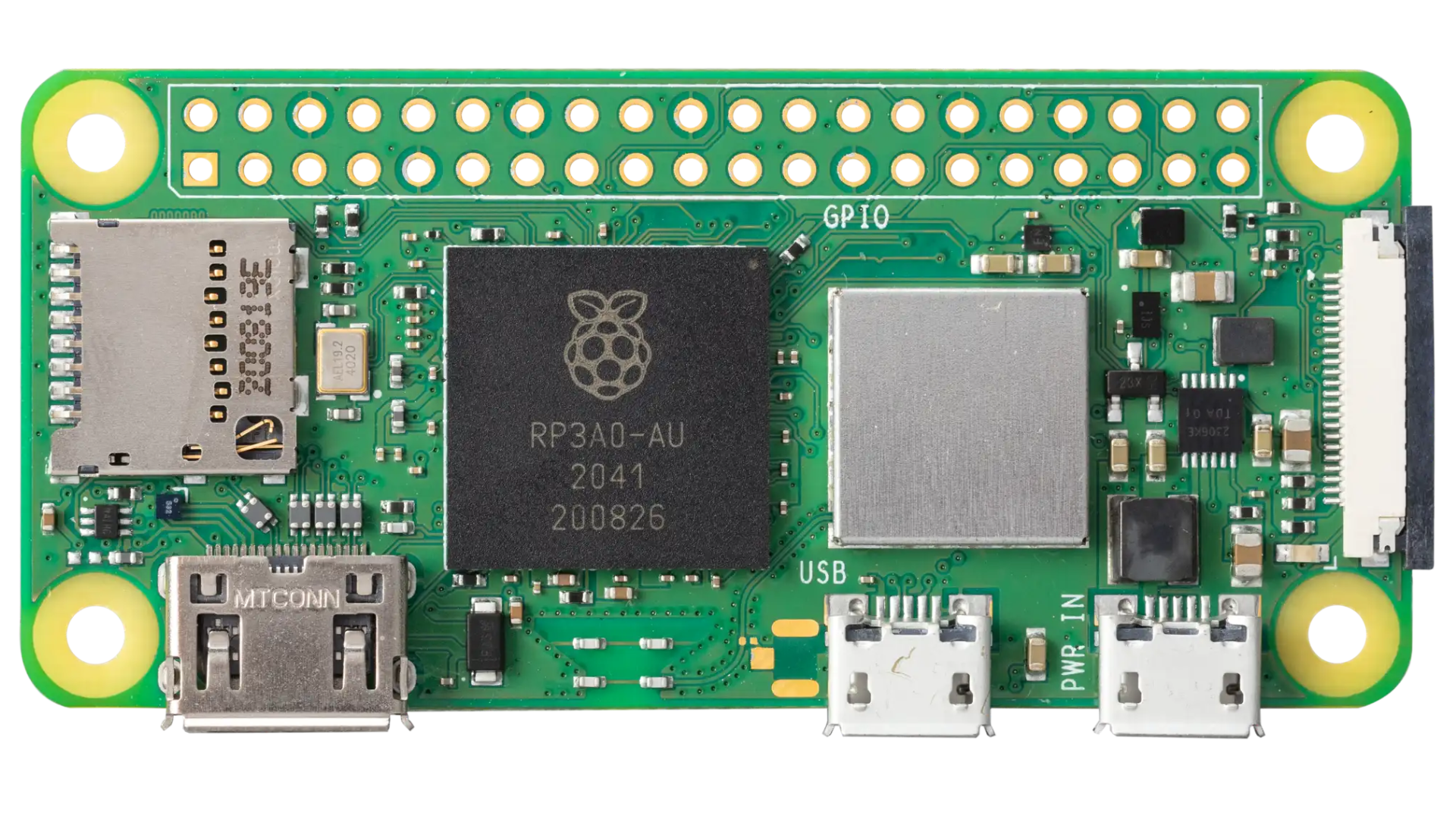
The Raspberry Pi Zero 2 W, manufactured by Raspberry, is a compact, low-cost single-board computer designed for a wide range of applications. It features a quad-core ARM Cortex-A53 processor, 512MB of RAM, built-in Wi-Fi and Bluetooth connectivity, and a versatile set of GPIO pins for hardware interfacing. Despite its small size, the Zero 2 W delivers impressive performance and flexibility, making it ideal for projects such as IoT devices, robotics, media centers, and more.
Explore Projects Built with Raspberry Pi Zero 2 W
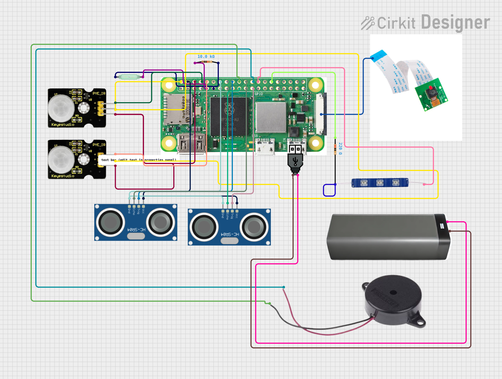
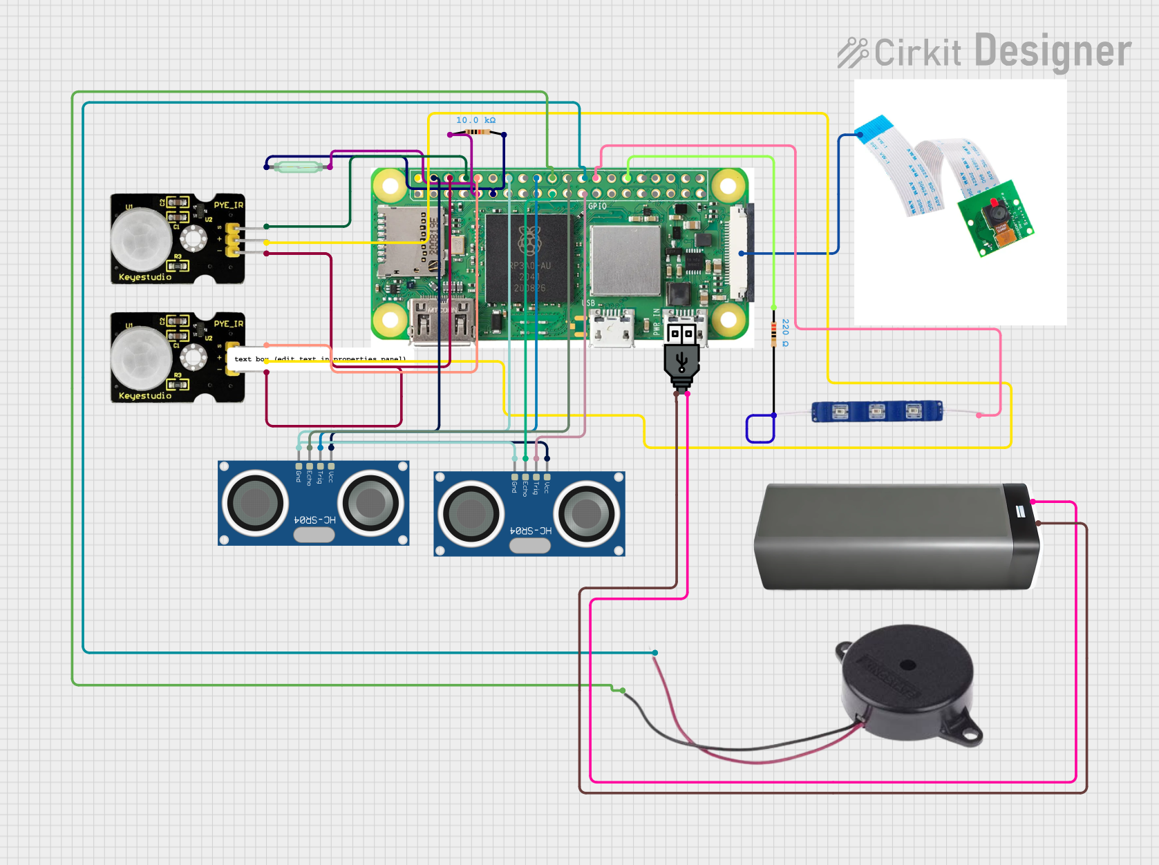
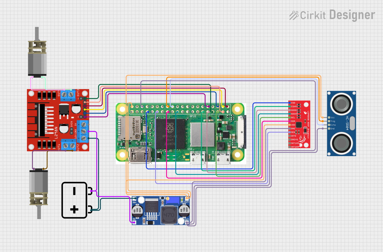
Explore Projects Built with Raspberry Pi Zero 2 W
Common Applications and Use Cases
- IoT (Internet of Things): Smart home devices, environmental monitoring, and automation.
- Robotics: Control systems for small robots and drones.
- Media Centers: Lightweight media streaming and playback using software like Kodi.
- Prototyping: Rapid development of hardware and software projects.
- Education: Teaching programming, electronics, and computer science concepts.
Technical Specifications
The Raspberry Pi Zero 2 W is packed with features that make it a powerful yet affordable computing platform. Below are its key technical details:
Key Technical Details
| Specification | Details |
|---|---|
| Processor | Quad-core ARM Cortex-A53, 1 GHz |
| RAM | 512MB LPDDR2 |
| Wireless Connectivity | 802.11 b/g/n Wi-Fi, Bluetooth 4.2, BLE |
| GPIO | 40-pin header (unpopulated) |
| Video Output | Mini HDMI (1080p at 30fps) |
| USB Ports | 1x Micro USB for data, 1x Micro USB for power |
| Storage | MicroSD card slot |
| Power Supply | 5V/2.5A via Micro USB |
| Dimensions | 65mm x 30mm x 5mm |
| Weight | 9g |
GPIO Pin Configuration
The Raspberry Pi Zero 2 W features a 40-pin GPIO header. Below is a summary of the pin configuration:
| Pin Number | Function | Description |
|---|---|---|
| 1 | 3.3V Power | 3.3V power supply |
| 2 | 5V Power | 5V power supply |
| 3 | GPIO2 (SDA1) | I2C Data |
| 4 | 5V Power | 5V power supply |
| 5 | GPIO3 (SCL1) | I2C Clock |
| 6 | Ground | Ground |
| ... | ... | ... (Refer to the official GPIO pinout) |
For the full GPIO pinout, refer to the official Raspberry Pi documentation.
Usage Instructions
How to Use the Raspberry Pi Zero 2 W in a Circuit
Powering the Board:
- Use a 5V/2.5A power supply connected to the Micro USB power port.
- Ensure the power supply is stable to avoid performance issues.
Connecting Peripherals:
- Use a Mini HDMI to HDMI adapter for video output.
- Connect a USB OTG adapter to the Micro USB data port for peripherals like keyboards or mice.
- Insert a preloaded MicroSD card with the Raspberry Pi OS or other compatible operating systems.
Using GPIO Pins:
- Solder a 40-pin header to the GPIO pads if needed.
- Use jumper wires to connect the GPIO pins to external components like LEDs, sensors, or motors.
Wireless Connectivity:
- Configure Wi-Fi and Bluetooth through the Raspberry Pi OS settings or via the terminal.
Important Considerations and Best Practices
- Heat Management: While the Zero 2 W is efficient, consider using a heatsink for prolonged high-performance tasks.
- Static Protection: Handle the board with care to avoid static discharge damage.
- Software Updates: Regularly update the Raspberry Pi OS to ensure security and compatibility.
Example: Blinking an LED with GPIO and Python
Below is an example of how to blink an LED connected to GPIO pin 17 using Python:
Import the necessary library for GPIO control
import RPi.GPIO as GPIO import time
Set up GPIO mode and pin
GPIO.setmode(GPIO.BCM) # Use Broadcom pin numbering GPIO.setup(17, GPIO.OUT) # Set GPIO pin 17 as an output
try: while True: GPIO.output(17, GPIO.HIGH) # Turn the LED on time.sleep(1) # Wait for 1 second GPIO.output(17, GPIO.LOW) # Turn the LED off time.sleep(1) # Wait for 1 second except KeyboardInterrupt: # Clean up GPIO settings on exit GPIO.cleanup()
**Note:** Connect the LED's anode to GPIO pin 17 and the cathode to a resistor (330Ω) in series with a ground pin.
Troubleshooting and FAQs
Common Issues and Solutions
The board does not power on:
- Ensure the power supply provides 5V/2.5A.
- Check the Micro USB power cable for damage or poor quality.
Wi-Fi is not connecting:
- Verify the Wi-Fi credentials in the Raspberry Pi OS settings.
- Ensure the router is within range and functioning properly.
GPIO pins are not working:
- Confirm the correct GPIO pin numbering (BCM vs. BOARD mode in Python).
- Check for loose connections or soldering issues.
The board overheats:
- Use a heatsink or active cooling if running intensive tasks for extended periods.
FAQs
Can I use the Raspberry Pi Zero 2 W for gaming?
- Yes, lightweight retro gaming is possible using emulators like RetroPie, but performance is limited compared to higher-end Raspberry Pi models.
What operating systems are compatible?
- The Raspberry Pi Zero 2 W supports Raspberry Pi OS, Ubuntu, and other lightweight Linux distributions.
Can I power the board via GPIO pins?
- Yes, you can supply 5V directly to the 5V and GND GPIO pins, but ensure proper voltage regulation.
For additional support, refer to the official Raspberry Pi documentation or community forums.