
How to Use COPPER COIL - 30 TURNS: Examples, Pinouts, and Specs
 Design with COPPER COIL - 30 TURNS in Cirkit Designer
Introduction
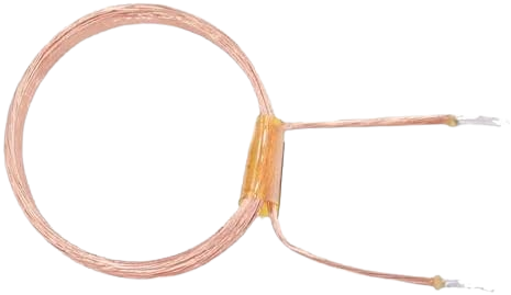
The Copper Coil - 30 Turns (Manufacturer: Default, Part ID: 200 TURNS) is a passive electronic component designed to generate magnetic fields or induce electromotive force (EMF) when an electric current flows through it. This coil consists of 30 tightly wound turns of copper wire, making it suitable for applications requiring inductance, electromagnetic coupling, or energy transfer.
Explore Projects Built with COPPER COIL - 30 TURNS
 Open Project in Cirkit Designer
 Open Project in Cirkit Designer
 Open Project in Cirkit Designer
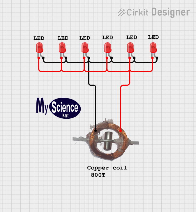 Open Project in Cirkit Designer
Explore Projects Built with COPPER COIL - 30 TURNS
Open Project in Cirkit DesignerOpen Project in Cirkit DesignerOpen Project in Cirkit DesignerOpen Project in Cirkit DesignerCommon Applications and Use Cases
- Electromagnetic field generation
- Inductive coupling in transformers
- Wireless power transfer systems
- RF circuits and antennas
- Inductors in filtering and tuning circuits
- Educational demonstrations of electromagnetic principles
Technical Specifications
Below are the key technical details for the Copper Coil - 30 Turns:
| Parameter | Value |
|---|---|
| Manufacturer | Default |
| Part ID | 200 TURNS |
| Number of Turns | 30 |
| Wire Material | Copper |
| Wire Gauge | 24 AWG |
| Coil Diameter | 10 mm |
| Inductance (Approx.) | 15 µH (varies with core type) |
| Maximum Current | 2 A |
| Resistance (Approx.) | 0.1 Ω |
| Operating Temperature | -40°C to 85°C |
Pin Configuration and Descriptions
The Copper Coil - 30 Turns has two terminals, as described below:
| Pin | Description |
|---|---|
| Pin 1 | Input terminal for current flow |
| Pin 2 | Output terminal for current flow |
Note: The polarity of the terminals does not matter for DC applications, but it may affect performance in AC or RF circuits.
Usage Instructions
How to Use the Copper Coil in a Circuit
- Determine the Application: Identify whether the coil will be used for inductance, electromagnetic coupling, or another purpose.
- Connect the Terminals: Solder or connect the two terminals of the coil to the circuit. Ensure a secure connection to avoid resistance or signal loss.
- Select a Core (Optional): For applications requiring higher inductance, insert a ferromagnetic core (e.g., iron or ferrite) into the coil.
- Power the Circuit: Apply the appropriate voltage and current to the circuit. Ensure the current does not exceed the maximum rating of 2 A.
Important Considerations and Best Practices
- Avoid Overheating: Prolonged use at high currents may cause the coil to overheat. Ensure proper ventilation or cooling if necessary.
- Core Selection: The inductance of the coil can be significantly increased by using a suitable core material. Choose a core based on the frequency and application requirements.
- AC vs. DC: For AC applications, consider the skin effect and frequency-dependent resistance of the copper wire.
- Mounting: Secure the coil to the circuit board or enclosure to prevent mechanical vibrations or movement.
Example: Using the Copper Coil with an Arduino UNO
The Copper Coil - 30 Turns can be used with an Arduino UNO to demonstrate electromagnetic induction. Below is an example of generating a magnetic field using the coil:
// Example: Generating a magnetic field with the Copper Coil - 30 Turns
// Connect one terminal of the coil to pin 9 of the Arduino UNO
// Connect the other terminal to GND

const int coilPin = 9; // Pin connected to the copper coil

void setup() {
  pinMode(coilPin, OUTPUT); // Set the coil pin as an output
}

void loop() {
  digitalWrite(coilPin, HIGH); // Energize the coil
  delay(1000);                // Keep the coil energized for 1 second
  digitalWrite(coilPin, LOW); // De-energize the coil
  delay(1000);                // Wait for 1 second before repeating
}
Note: This example demonstrates basic on/off control of the coil. For more advanced applications, such as generating AC signals, use a PWM signal or an external driver circuit.
Troubleshooting and FAQs
Common Issues and Solutions
| Issue | Solution |
|---|---|
| Coil overheating | Ensure the current does not exceed 2 A. Use a heat sink or cooling mechanism if needed. |
| Low inductance or weak magnetic field | Insert a ferromagnetic core into the coil to increase inductance. |
| Poor connection or signal loss | Check solder joints and ensure secure connections to the terminals. |
| Coil not functioning in AC circuits | Verify the frequency and ensure the coil is compatible with the application. |
FAQs
Can I use this coil for high-frequency applications?
- Yes, but consider the skin effect and use a core material optimized for high frequencies.
What happens if I exceed the maximum current rating?
- Exceeding 2 A may cause the coil to overheat, potentially damaging the insulation or wire.
Can I use this coil without a core?
- Yes, the coil can function without a core, but the inductance will be lower.
How do I calculate the inductance of the coil?
- Use the formula ( L = \frac{{N^2 \cdot \mu \cdot A}}{{l}} ), where ( N ) is the number of turns, ( \mu ) is the permeability of the core material, ( A ) is the cross-sectional area, and ( l ) is the length of the coil.
By following this documentation, users can effectively integrate the Copper Coil - 30 Turns into their projects and troubleshoot common issues.