How to Use PCF8591 : Examples, Pinouts, and Specs
Introduction
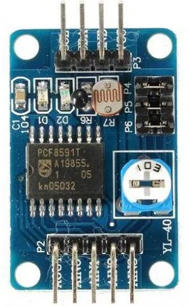
The PCF8591 is a versatile 4-channel, 8-bit analog-to-digital converter (ADC) and digital-to-analog converter (DAC) manufactured by Analog Devices. It is designed to interface with microcontrollers and other digital systems via the I2C communication protocol. This component is ideal for applications requiring the conversion of analog signals to digital data and vice versa, such as sensor interfacing, signal processing, and control systems.
Explore Projects Built with PCF8591

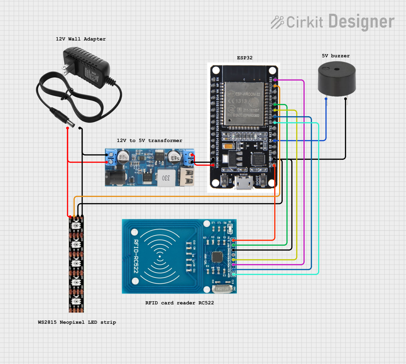
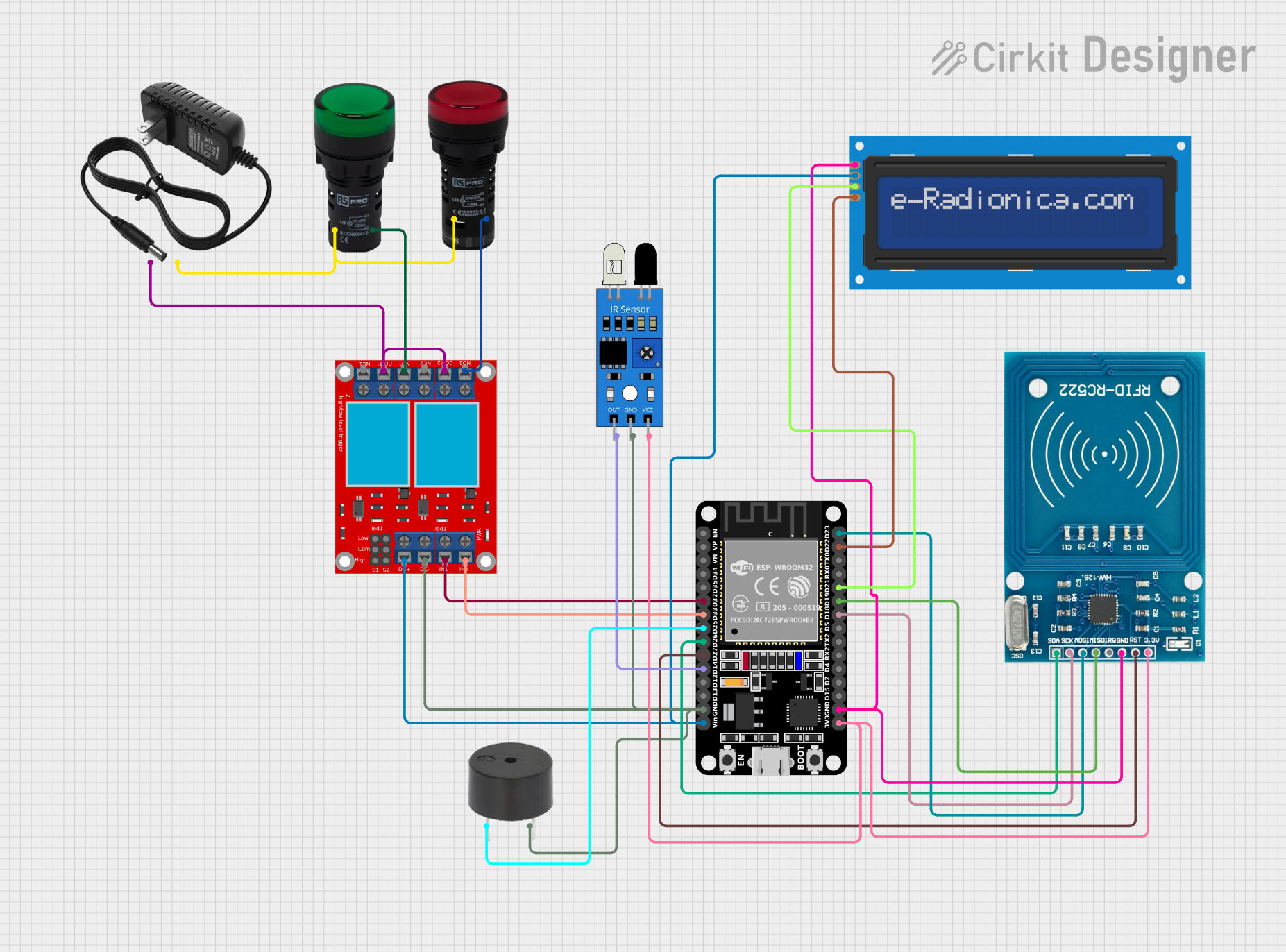

Explore Projects Built with PCF8591
Common Applications and Use Cases
- Sensor data acquisition (e.g., temperature, light, or pressure sensors)
- Signal monitoring and processing
- Analog signal generation for control systems
- Educational and prototyping projects with microcontrollers (e.g., Arduino, Raspberry Pi)
Technical Specifications
The following table outlines the key technical details of the PCF8591:
| Parameter | Value |
|---|---|
| Supply Voltage (Vcc) | 2.5V to 6V |
| Analog Input Channels | 4 |
| Resolution (ADC/DAC) | 8-bit |
| Maximum Sampling Rate | 11 kHz (at 5V supply) |
| Communication Protocol | I2C |
| I2C Address Range | 0x48 to 0x4F (configurable via A0-A2 pins) |
| Operating Temperature Range | -40°C to +85°C |
| Package Type | DIP-8, SO-8 |
Pin Configuration and Descriptions
The PCF8591 has 8 pins, as described in the table below:
| Pin Number | Pin Name | Description |
|---|---|---|
| 1 | A0 | I2C address selection bit 0 |
| 2 | A1 | I2C address selection bit 1 |
| 3 | A2 | I2C address selection bit 2 |
| 4 | VSS | Ground (0V reference) |
| 5 | SDA | Serial Data Line for I2C communication |
| 6 | SCL | Serial Clock Line for I2C communication |
| 7 | VDD | Positive supply voltage |
| 8 | AOUT | Analog output from the DAC |
Usage Instructions
How to Use the PCF8591 in a Circuit
- Power Supply: Connect the VDD pin to a 2.5V–6V power source and the VSS pin to ground.
- I2C Address Configuration: Use the A0, A1, and A2 pins to set the I2C address. These pins can be connected to VDD or VSS to configure the address (e.g., all grounded = 0x48).
- I2C Communication: Connect the SDA and SCL pins to the corresponding I2C pins on your microcontroller. Use pull-up resistors (typically 4.7kΩ) on these lines.
- Analog Inputs: Connect up to four analog signals to the ADC input channels (AIN0 to AIN3). The PCF8591 will convert these signals to digital values.
- Analog Output: Use the AOUT pin to output an analog signal generated by the DAC.
Important Considerations and Best Practices
- Ensure the I2C pull-up resistors are properly connected to avoid communication issues.
- The maximum input voltage for the analog channels should not exceed the supply voltage (VDD).
- The DAC output (AOUT) is limited to the range of 0V to VDD.
- Use decoupling capacitors (e.g., 0.1µF) near the VDD pin to reduce noise.
Example: Using PCF8591 with Arduino UNO
Below is an example of how to read an analog input and output a signal using the PCF8591 with an Arduino UNO:
#include <Wire.h> // Include the Wire library for I2C communication

#define PCF8591_ADDRESS 0x48 // Default I2C address of PCF8591

void setup() {
  Wire.begin(); // Initialize I2C communication
  Serial.begin(9600); // Initialize serial communication for debugging
}

void loop() {
  // Read analog input from channel 0
  Wire.beginTransmission(PCF8591_ADDRESS);
  Wire.write(0x40); // Control byte: enable ADC, select channel 0
  Wire.endTransmission();

  Wire.requestFrom(PCF8591_ADDRESS, 2); // Request 2 bytes (dummy + actual data)
  Wire.read(); // Discard the first byte (dummy read)
  int analogValue = Wire.read(); // Read the actual ADC value (0-255)

  Serial.print("Analog Input (AIN0): ");
  Serial.println(analogValue);

  // Output an analog signal using the DAC
  Wire.beginTransmission(PCF8591_ADDRESS);
  Wire.write(0x40); // Control byte: enable DAC
  Wire.write(analogValue); // Write the value to the DAC
  Wire.endTransmission();

  delay(500); // Wait for 500ms before the next reading
}
Troubleshooting and FAQs
Common Issues
No I2C Communication:
- Ensure the SDA and SCL lines are connected correctly and have pull-up resistors.
- Verify the I2C address matches the configuration of the A0, A1, and A2 pins.
Incorrect ADC Readings:
- Check that the input voltage on the analog channels does not exceed the supply voltage (VDD).
- Ensure proper grounding of the circuit to avoid noise interference.
No DAC Output:
- Verify that the control byte sent to the PCF8591 enables the DAC.
- Ensure the AOUT pin is not shorted or improperly connected.
FAQs
Q: Can I use the PCF8591 with a 3.3V microcontroller?
A: Yes, the PCF8591 operates with supply voltages as low as 2.5V, making it compatible with 3.3V systems.
Q: What is the resolution of the ADC and DAC?
A: Both the ADC and DAC have an 8-bit resolution, meaning they can represent values from 0 to 255.
Q: How do I connect multiple PCF8591 devices on the same I2C bus?
A: Configure each device with a unique I2C address by setting the A0, A1, and A2 pins to different combinations of VDD and VSS.
Q: Can the PCF8591 handle negative input voltages?
A: No, the input voltage range is 0V to VDD. Negative voltages may damage the device.