How to Use V_REG_MIC5235: Examples, Pinouts, and Specs
Introduction
The V_REG_MIC5235 is a low dropout (LDO) voltage regulator capable of providing a fixed output voltage with low power dissipation. This component is particularly useful in battery-powered and portable electronic devices where efficient power management is crucial. The V_REG_MIC5235 is known for its low quiescent current and stable operation over a wide range of input voltages and load conditions, making it a popular choice for extending battery life and ensuring consistent performance.
Explore Projects Built with V_REG_MIC5235
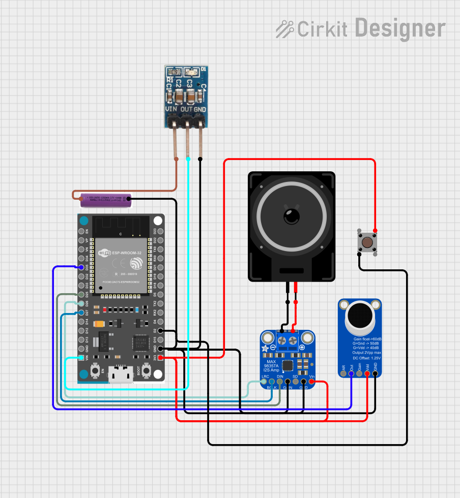
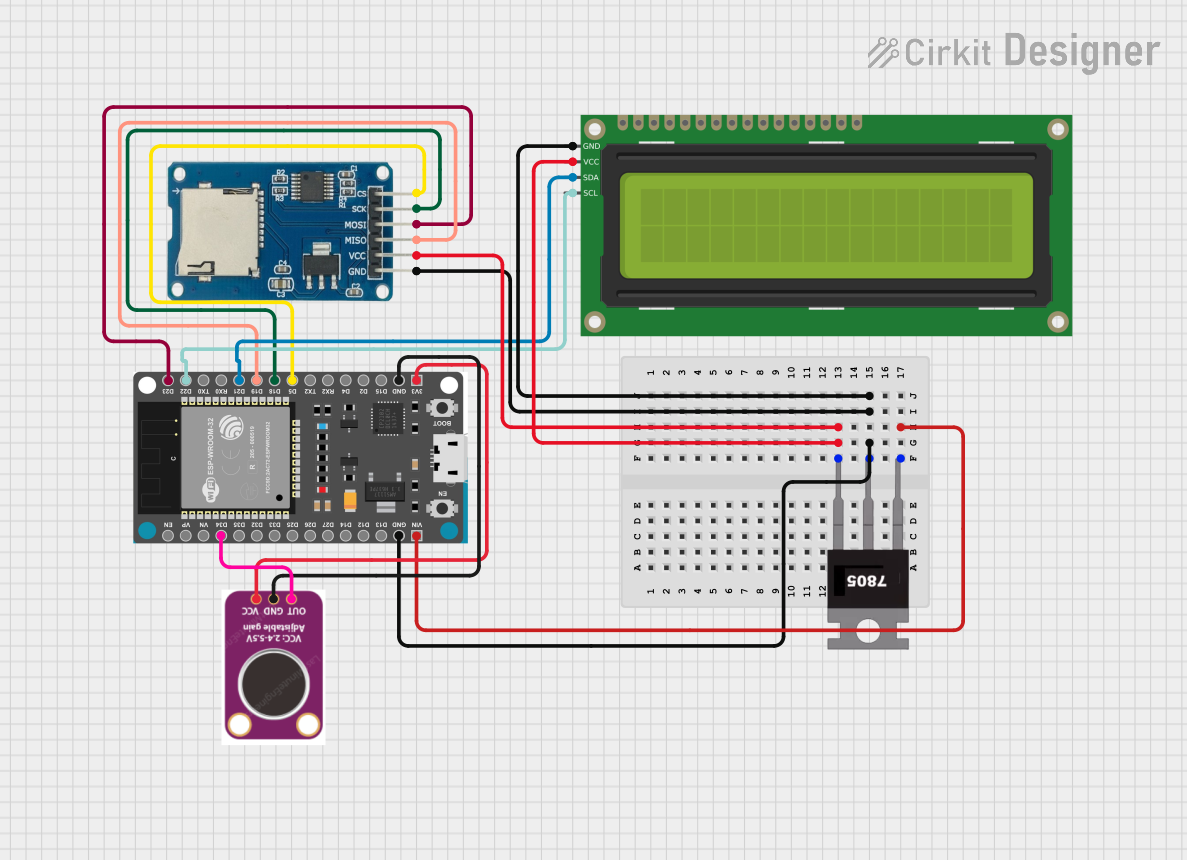
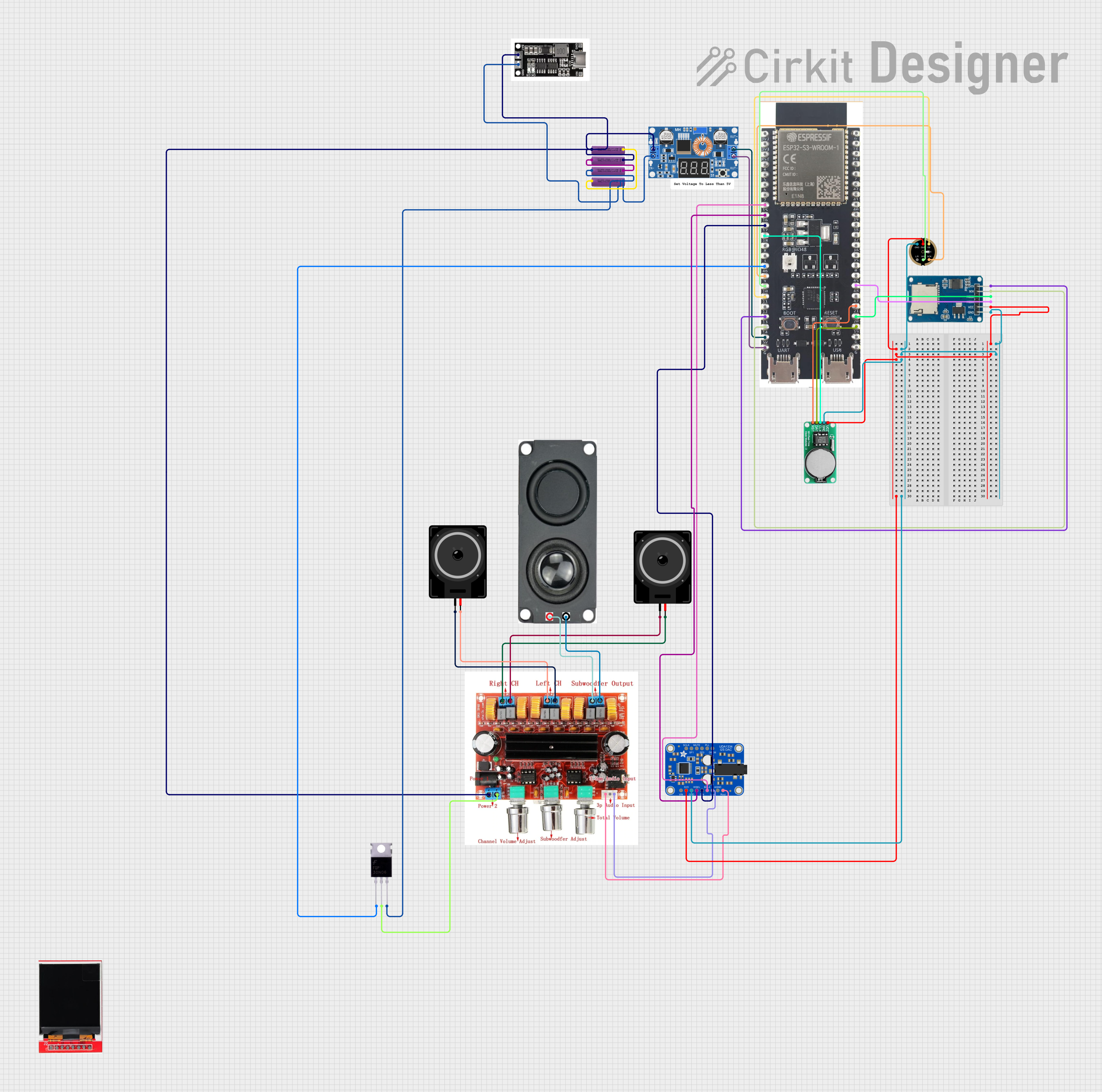
Explore Projects Built with V_REG_MIC5235
Common Applications and Use Cases
- Battery-powered devices
- Portable electronics
- Microcontroller power supply
- Low-power analog circuits
- Reference voltage sources
Technical Specifications
Key Technical Details
- Output Voltage: Fixed (varies by part number)
- Maximum Input Voltage: 16V
- Output Current: Up to 150mA
- Dropout Voltage: Typically 165mV at 150mA load
- Quiescent Current: Typically 110µA
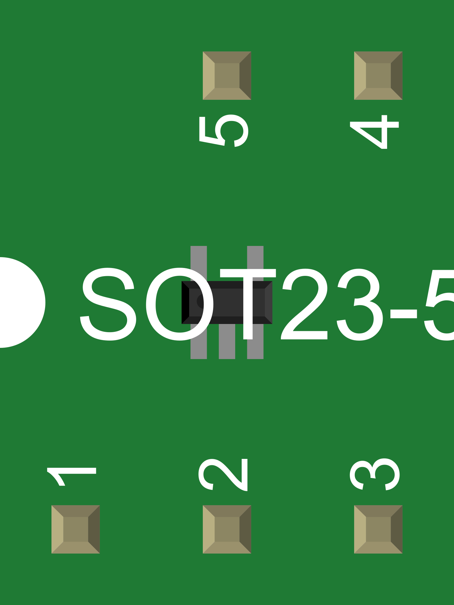
- Package: SOT-23-5
Pin Configuration and Descriptions
| Pin Number | Name | Description |
|---|---|---|
| 1 | IN | Input voltage supply. Connect to the source voltage. |
| 2 | GND | Ground reference for the regulator. |
| 3 | NC | No connection. This pin is not internally connected. |
| 4 | BYP | Bypass pin. Connect a small capacitor (e.g., 1nF) to GND to reduce output noise. |
| 5 | OUT | Regulated output voltage. Connect to the load. |
Usage Instructions
How to Use the V_REG_MIC5235 in a Circuit
- Connect the input voltage (up to 16V) to the IN pin.
- Connect the GND pin to the system ground.
- Optionally, connect a 1nF capacitor between the BYP pin and GND to reduce output noise.
- Connect the load to the OUT pin.
- Place a capacitor (typically 1µF or greater) close to the OUT pin to stabilize the output voltage.
Important Considerations and Best Practices
- Ensure that the input voltage does not exceed the maximum rating of 16V.
- The output capacitor is critical for stability; choose a capacitor with low equivalent series resistance (ESR).
- Avoid placing high-current switching devices near the LDO to prevent noise coupling.
- Keep the input and output capacitors as close to the LDO as possible to minimize parasitic inductance.
- Use a heat sink if the power dissipation is expected to be high due to a large difference between input and output voltage or high output current.
Troubleshooting and FAQs
Common Issues Users Might Face
- Output Voltage Instability: Ensure that the output capacitor meets the minimum required value and has low ESR.
- Excessive Power Dissipation: Check if the input voltage is too high or if the output current is approaching the maximum limit. Consider using a heat sink.
- Output Noise: Verify the bypass capacitor is installed and functioning. Keep the LDO away from high-frequency switching signals.
Solutions and Tips for Troubleshooting
- If the output voltage is incorrect, verify the input voltage and the integrity of the connections.
- For thermal issues, improve airflow, add a heat sink, or reduce the load current.
- If the LDO is not regulating, check for short circuits or insufficient input voltage.
FAQs
Q: Can I use the V_REG_MIC5235 without a bypass capacitor? A: While the bypass capacitor is optional, it is recommended to use one to improve noise performance.
Q: What is the maximum output current of the V_REG_MIC5235? A: The V_REG_MIC5235 can supply up to 150mA of output current.
Q: How do I choose the output capacitor? A: The output capacitor should be at least 1µF with low ESR for stability. Ceramic capacitors are typically a good choice.
Example Connection with Arduino UNO
The V_REG_MIC5235 can be used to provide a regulated voltage to an Arduino UNO board or its peripherals. Below is an example of how to connect the V_REG_MIC5235 to an Arduino UNO:
// No specific code is required for the basic operation of the V_REG_MIC5235
// as it is a hardware component. However, ensure that the regulated voltage
// is compatible with the Arduino UNO's operating voltage if powering the board.
Note: When using the V_REG_MIC5235 to power an Arduino UNO, ensure that the output voltage of the V_REG_MIC5235 matches the required input voltage of the Arduino UNO (typically 5V or 3.3V, depending on the model). Always consult the datasheet of the specific V_REG_MIC5235 part number you are using to verify the output voltage.