How to Use WS2812b RGB Matrix 16x16 (256 LED): Examples, Pinouts, and Specs
Introduction
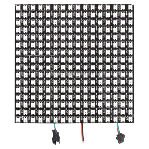
The WS2812b RGB Matrix 16x16 (Manufacturer Part ID: WS2812B-16x16-Matrix) is a compact LED matrix manufactured by Worldsemi. It consists of 256 individually addressable RGB LEDs arranged in a 16x16 grid. Each LED is capable of displaying 24-bit color, allowing for vibrant and dynamic visual effects. The matrix is controlled via a single data line, making it easy to integrate into a variety of projects.
Explore Projects Built with WS2812b RGB Matrix 16x16 (256 LED)


Explore Projects Built with WS2812b RGB Matrix 16x16 (256 LED)
Common Applications and Use Cases
- Decorative lighting and signage
- Animated displays and visual effects
- Wearable technology
- Interactive art installations
- DIY projects and prototyping
- Gaming setups and PC case lighting
Technical Specifications
Below are the key technical details for the WS2812b RGB Matrix 16x16:
| Parameter | Value |
|---|---|
| Manufacturer | Worldsemi |
| Part ID | WS2812B-16x16-Matrix |
| LED Count | 256 (16x16 grid) |
| LED Type | WS2812b (RGB, individually addressable) |
| Input Voltage | 5V DC |
| Power Consumption | ~60mA per LED (max brightness, white) |
| Communication Protocol | One-wire (serial) |
| Data Input Signal Voltage | 3.3V to 5V |
| Refresh Rate | ~400Hz |
| Dimensions | 160mm x 160mm |
| Operating Temperature | -25°C to +80°C |
Pin Configuration and Descriptions
The WS2812b RGB Matrix 16x16 has three main pins for operation:
| Pin Name | Description | Notes |
|---|---|---|
| VCC | Power supply input (5V DC) | Connect to a stable 5V power source |
| GND | Ground | Common ground for power and data |
| DIN | Data input | Connect to the microcontroller's data output |
Note: Some matrices may also have a DOUT pin for chaining multiple matrices together. This pin outputs the data signal for the next matrix in the chain.
Usage Instructions
How to Use the Component in a Circuit
- Power Supply: Connect the VCC pin to a 5V DC power source and the GND pin to ground. Ensure the power supply can handle the total current draw of the matrix (up to ~15A at full brightness).
- Data Connection: Connect the DIN pin to the data output pin of your microcontroller. A resistor (330-470Ω) is recommended between the microcontroller and the DIN pin to protect the data line.
- Capacitor: Place a 1000µF capacitor across the VCC and GND pins to stabilize the power supply and prevent voltage spikes.
- Programming: Use a library like Adafruit NeoPixel or FastLED to control the LEDs. These libraries simplify communication with the WS2812b protocol.
Important Considerations and Best Practices
- Power Management: At full brightness, the matrix can draw significant current. Use a power supply capable of delivering sufficient current.
- Heat Dissipation: Prolonged use at high brightness may generate heat. Ensure proper ventilation or heat dissipation.
- Signal Integrity: Keep the data line as short as possible to avoid signal degradation. For longer distances, use a level shifter to ensure a 5V data signal.
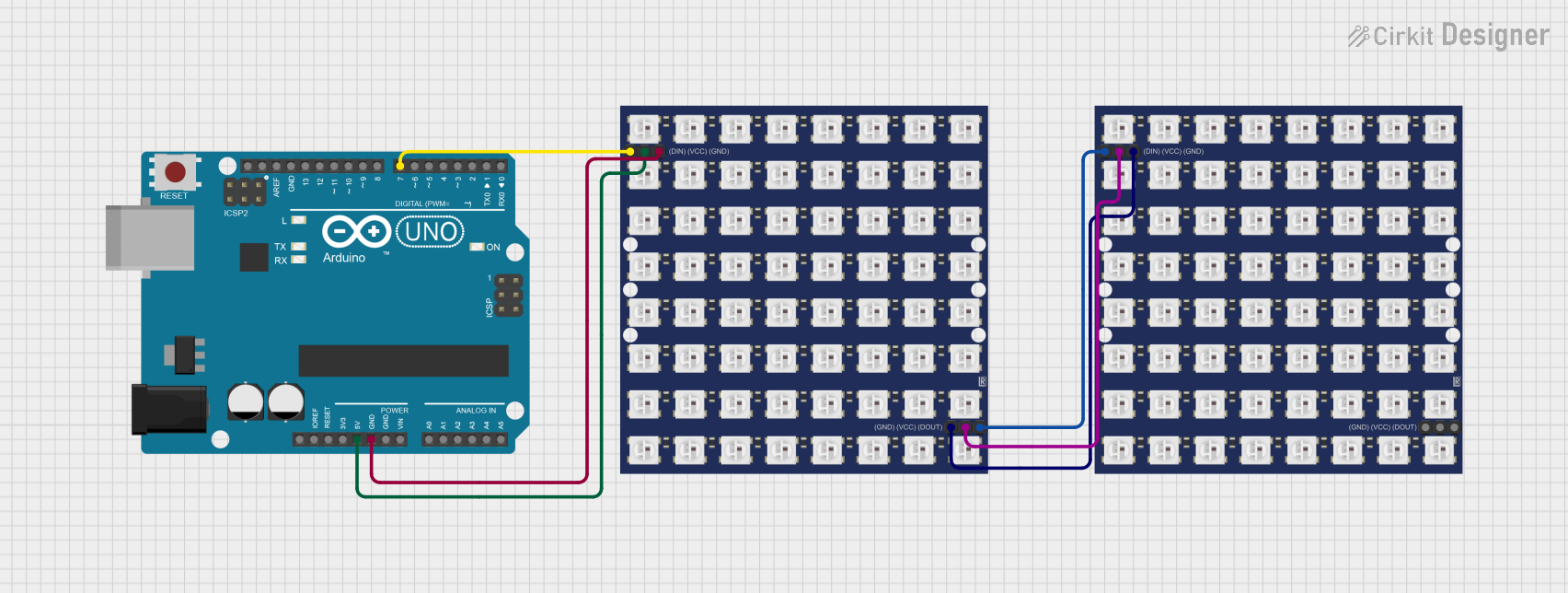
- Chaining Matrices: If chaining multiple matrices, connect the DOUT pin of the first matrix to the DIN pin of the next.
Example Code for Arduino UNO
Below is an example of how to control the WS2812b RGB Matrix 16x16 using the Adafruit NeoPixel library:
#include <Adafruit_NeoPixel.h>

// Define the number of LEDs in the matrix
#define NUM_LEDS 256

// Define the data pin connected to the DIN pin of the matrix
#define DATA_PIN 6

// Create a NeoPixel object
Adafruit_NeoPixel matrix = Adafruit_NeoPixel(NUM_LEDS, DATA_PIN, NEO_GRB + NEO_KHZ800);

void setup() {
  matrix.begin(); // Initialize the NeoPixel library
  matrix.show();  // Turn off all LEDs initially
}

void loop() {
  // Example: Light up the matrix with a red color
  for (int i = 0; i < NUM_LEDS; i++) {
    matrix.setPixelColor(i, matrix.Color(255, 0, 0)); // Set each LED to red
  }
  matrix.show(); // Update the matrix to display the color
  delay(1000);   // Wait for 1 second

  // Example: Turn off all LEDs
  for (int i = 0; i < NUM_LEDS; i++) {
    matrix.setPixelColor(i, matrix.Color(0, 0, 0)); // Turn off each LED
  }
  matrix.show(); // Update the matrix to turn off the LEDs
  delay(1000);   // Wait for 1 second
}
Note: Install the Adafruit NeoPixel library in the Arduino IDE before uploading the code.
Troubleshooting and FAQs
Common Issues and Solutions
LEDs Not Lighting Up
- Cause: Incorrect wiring or insufficient power supply.
- Solution: Double-check all connections, ensure the power supply is 5V and can handle the current draw.
Flickering or Incorrect Colors
- Cause: Signal degradation or noise on the data line.
- Solution: Add a 330-470Ω resistor on the data line and ensure the data wire is as short as possible.
Matrix Overheating
- Cause: Prolonged use at high brightness.
- Solution: Reduce brightness in the code or improve ventilation.
Data Signal Not Reaching the Matrix
- Cause: Voltage mismatch between the microcontroller and the matrix.
- Solution: Use a level shifter to convert the microcontroller's 3.3V signal to 5V.
FAQs
Q: Can I chain multiple WS2812b matrices together?
A: Yes, connect the DOUT pin of one matrix to the DIN pin of the next. Ensure the power supply can handle the combined current draw.
Q: What is the maximum distance for the data line?
A: For reliable operation, keep the data line under 1 meter. Use a level shifter for longer distances.
Q: Can I power the matrix directly from the Arduino?
A: No, the Arduino cannot supply enough current. Use an external 5V power supply.
Q: How do I display animations on the matrix?
A: Use libraries like Adafruit NeoPixel or FastLED to create and control animations programmatically.