How to Use Sensor LDR LM393: Examples, Pinouts, and Specs
Introduction
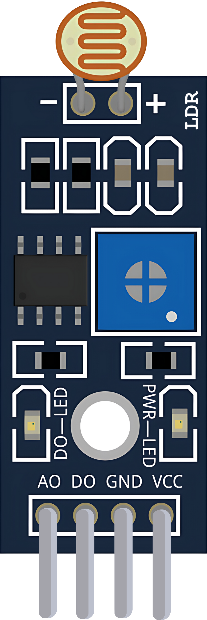
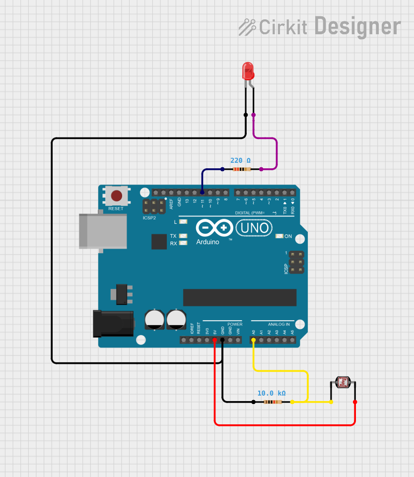
The Sensor LDR LM393 is a light sensing module that combines a Light Dependent Resistor (LDR) with an LM393 comparator to provide a digital output signal indicating light intensity. This sensor is widely used in applications such as automatic lighting control, security systems, and environmental monitoring.
Explore Projects Built with Sensor LDR LM393
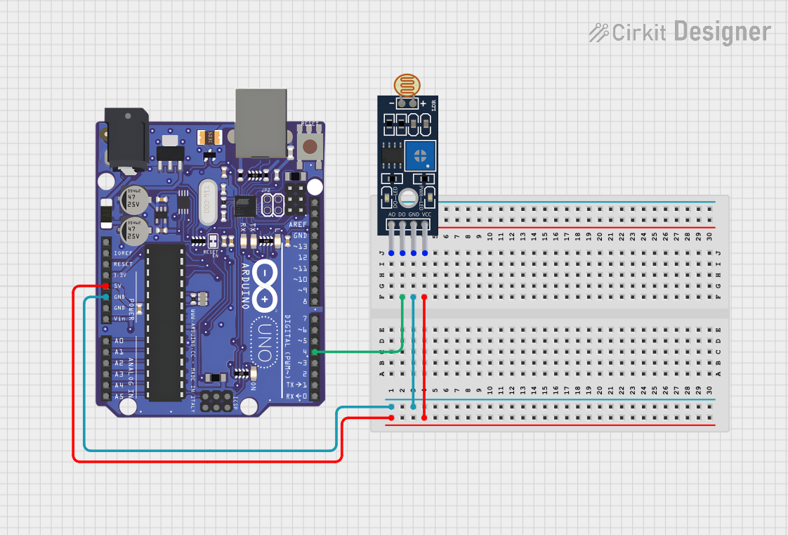
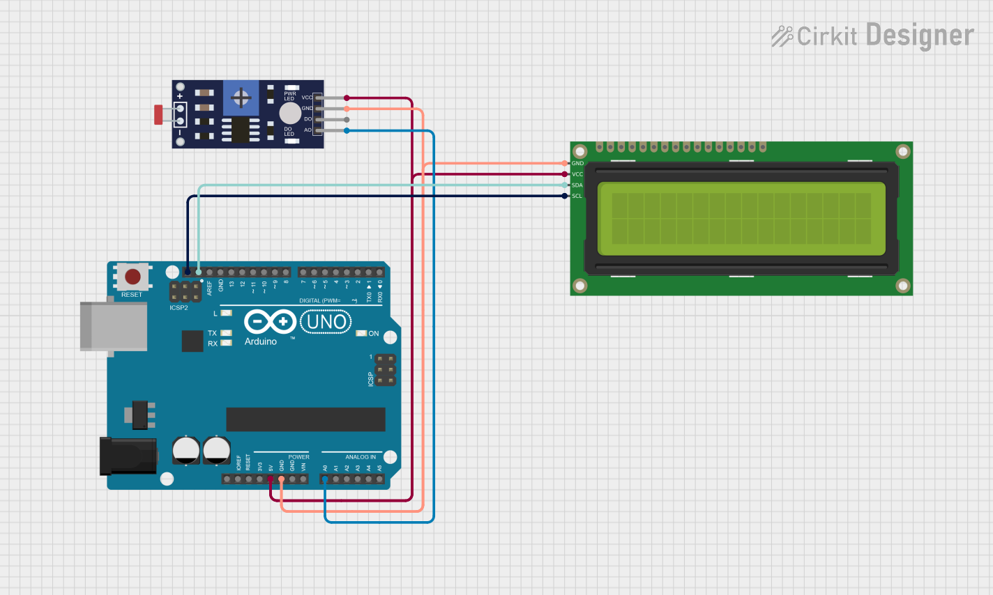
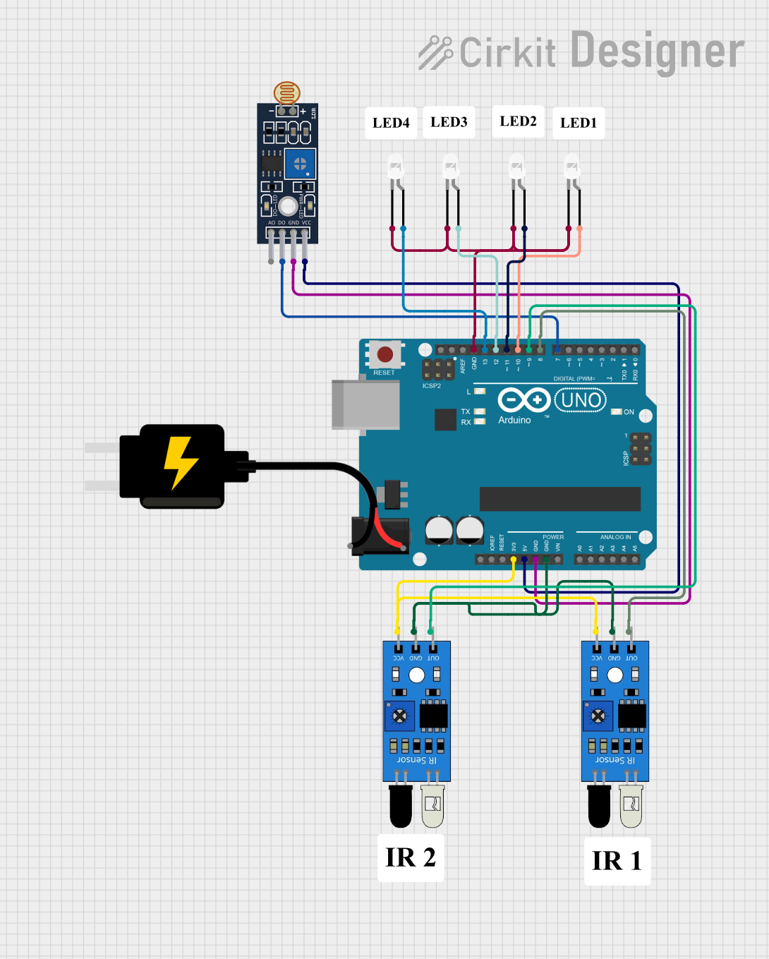
Explore Projects Built with Sensor LDR LM393
Common Applications and Use Cases
- Automatic night lights
- Security systems with light-based triggering
- Light level monitoring for agricultural applications
- Robotics for light-following or light-avoidance
- Educational projects to demonstrate light sensing technology
Technical Specifications
Key Technical Details
- Operating Voltage: 3.3V to 5V
- Output Type: Digital signal
- Comparator: LM393
- Sensitivity: Adjustable via onboard potentiometer
- Response Time: Dependent on LDR characteristics (typically tens of milliseconds)
- Operating Temperature: -20°C to 70°C
Pin Configuration and Descriptions
| Pin Number | Name | Description |
|---|---|---|
| 1 | VCC | Power supply (3.3V to 5V) |
| 2 | GND | Ground connection |
| 3 | DO | Digital output signal |
| 4 | AO | Analog output (not used with LM393) |
Usage Instructions
How to Use the Component in a Circuit
- Connect the VCC pin to the power supply (3.3V to 5V).
- Connect the GND pin to the ground of the power supply.
- Connect the DO pin to a digital input pin on a microcontroller, such as an Arduino UNO.
Important Considerations and Best Practices
- Ensure that the power supply voltage does not exceed the recommended operating voltage.
- Adjust the onboard potentiometer to set the threshold level for the digital output.
- Avoid placing the sensor in direct sunlight or near strong light sources that may saturate the LDR.
- Use a pull-up resistor if the microcontroller input pin is not internally pulled up.
Example Code for Arduino UNO
// Define the LDR sensor digital output pin
const int LDRPin = 2;

void setup() {
  pinMode(LDRPin, INPUT); // Set the LDR sensor pin as input
  Serial.begin(9600);     // Start serial communication at 9600 baud rate
}

void loop() {
  int sensorValue = digitalRead(LDRPin); // Read the sensor value
  // Print the sensor value to the Serial Monitor
  Serial.println(sensorValue);
  delay(500); // Wait for 500 milliseconds
}
Troubleshooting and FAQs
Common Issues Users Might Face
- Sensor not responding: Ensure that all connections are secure and the power supply is within the specified range.
- Inconsistent readings: Check if the onboard potentiometer is properly adjusted for the ambient light conditions.
- No output signal: Verify that the sensor is not exposed to excessive light that may be beyond its sensing capability.
Solutions and Tips for Troubleshooting
- If the sensor is not responding, double-check the wiring and ensure that the power supply is correctly connected.
- For inconsistent readings, adjust the sensitivity of the sensor using the onboard potentiometer.
- If there is no output signal, try reducing the light intensity or adjusting the potentiometer to a more sensitive setting.
FAQs
Q: Can I use the analog output (AO) with the LM393? A: No, the AO pin is not functional when using the LM393 comparator. The digital output (DO) should be used.
Q: How do I adjust the sensitivity of the sensor? A: Turn the onboard potentiometer clockwise to increase sensitivity (lower light threshold) or counterclockwise to decrease sensitivity (higher light threshold).
Q: What is the purpose of the LM393 in this sensor module? A: The LM393 comparator is used to compare the voltage level from the LDR with a reference voltage set by the potentiometer, providing a digital output when the light level crosses the threshold.