How to Use Relay 12v: Examples, Pinouts, and Specs
Introduction
A relay is an electromechanical switch that uses an electromagnetic coil to open or close a circuit. The 12V relay is specifically designed to operate with a 12-volt power supply. It acts as an intermediary device, allowing low-power control signals to manage high-power circuits. This makes it ideal for applications where isolation between control and load circuits is required.
Explore Projects Built with Relay 12v


Explore Projects Built with Relay 12v
Common Applications and Use Cases
- Home automation systems (e.g., controlling lights, fans, or appliances)
- Automotive electronics (e.g., controlling headlights, horns, or motors)
- Industrial control systems
- Microcontroller-based projects (e.g., Arduino or Raspberry Pi)
- Safety circuits requiring electrical isolation
Technical Specifications
Below are the key technical details of a standard 12V relay:
| Parameter | Value |
|---|---|
| Operating Voltage | 12V DC |
| Coil Resistance | ~400Ω to 500Ω (varies by model) |
| Switching Voltage (Load) | Up to 250V AC or 30V DC |
| Switching Current (Load) | Typically 10A (varies by model) |
| Contact Type | SPDT (Single Pole Double Throw) or DPDT (Double Pole Double Throw) |
| Isolation | Electrical isolation between control and load circuits |
| Dimensions | Varies (e.g., 28mm x 10mm x 15mm for common models) |
| Operating Temperature | -40°C to +85°C |
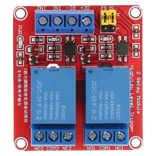
Pin Configuration and Descriptions
The 12V relay typically has 5 pins for SPDT relays. Below is the pinout description:
| Pin Name | Description |
|---|---|
| Coil (+) | Positive terminal of the relay coil. Connect to 12V DC. |
| Coil (-) | Negative terminal of the relay coil. Connect to ground. |
| Common (COM) | Common terminal for the load circuit. |
| Normally Open (NO) | Load terminal that remains disconnected when the relay is inactive. It connects to COM when the relay is activated. |
| Normally Closed (NC) | Load terminal that remains connected to COM when the relay is inactive. It disconnects when the relay is activated. |
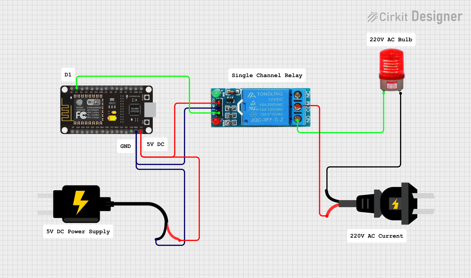
Usage Instructions
How to Use the Relay in a Circuit
- Power the Relay Coil: Connect the
Coil (+)pin to a 12V DC power source and theCoil (-)pin to ground. This energizes the relay coil when activated. - Control the Load Circuit:
- Connect the load device (e.g., a light bulb or motor) to the
COMandNOpins if you want the load to turn on when the relay is activated. - Alternatively, connect the load to the
COMandNCpins if you want the load to turn off when the relay is activated.
- Connect the load device (e.g., a light bulb or motor) to the
- Control Signal: Use a microcontroller or switch to control the relay coil. For microcontroller-based projects, use a transistor or relay driver circuit to handle the current required by the relay coil.
Important Considerations and Best Practices
- Use a Flyback Diode: Always connect a flyback diode (e.g., 1N4007) across the relay coil terminals to protect the circuit from voltage spikes caused by the collapsing magnetic field when the relay is deactivated.
- Check Load Ratings: Ensure the relay's voltage and current ratings match the requirements of your load circuit.
- Isolation: Use optocouplers or relay driver modules for additional isolation when interfacing with sensitive microcontrollers.
- Power Supply: Provide a stable 12V DC power supply to the relay coil to ensure reliable operation.
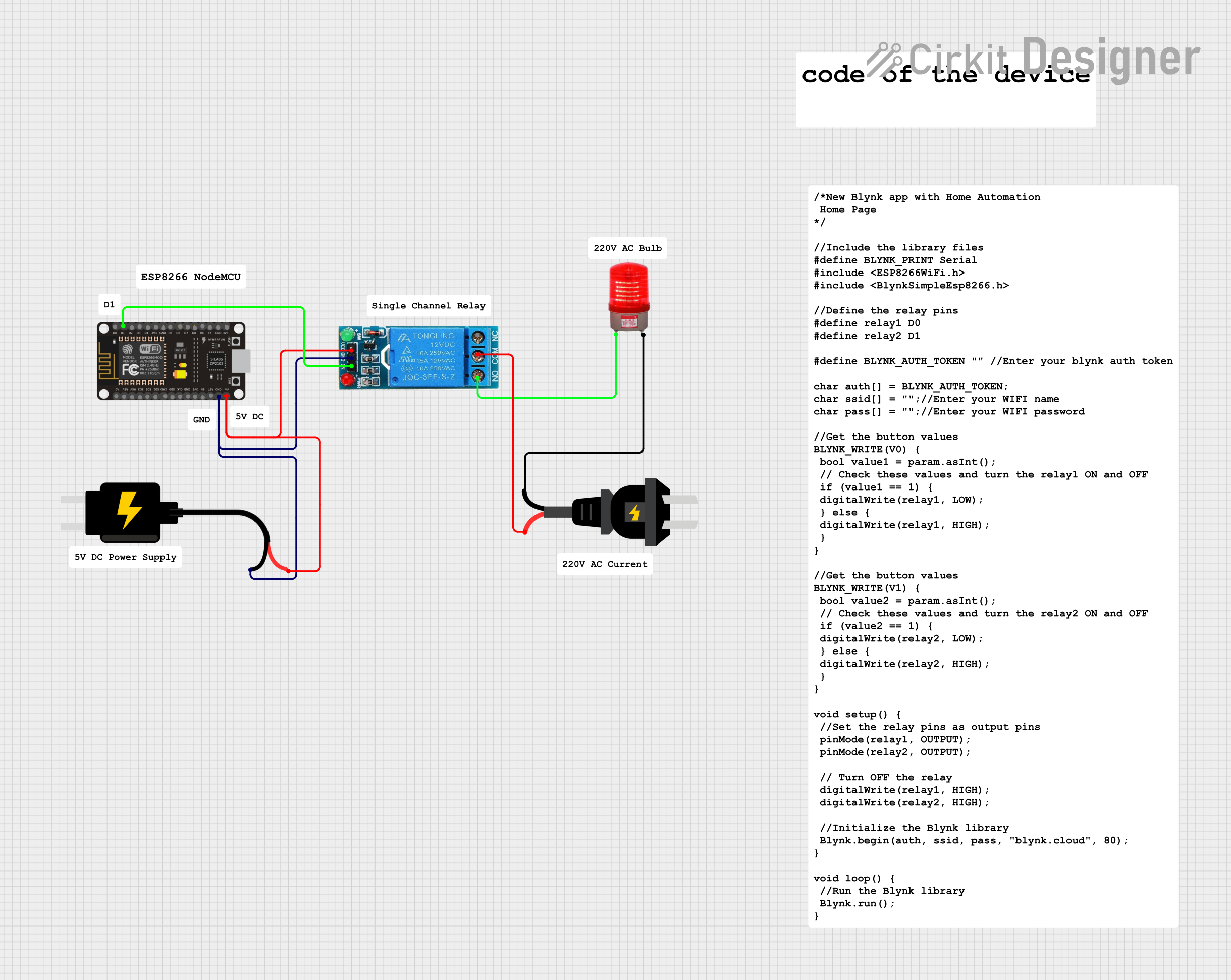
Example: Connecting a 12V Relay to an Arduino UNO
Below is an example of how to control a 12V relay using an Arduino UNO:
Circuit Connections
- Connect the
Coil (+)pin of the relay to the 12V power supply. - Connect the
Coil (-)pin to the collector of an NPN transistor (e.g., 2N2222). - Connect the emitter of the transistor to ground.
- Connect a 1kΩ resistor between the Arduino digital pin (e.g., pin 7) and the base of the transistor.
- Place a flyback diode (e.g., 1N4007) across the relay coil terminals, with the cathode connected to
Coil (+)and the anode toCoil (-). - Connect the load circuit to the
COMandNOpins of the relay.
Arduino Code
// Define the relay control pin
const int relayPin = 7;

void setup() {
  pinMode(relayPin, OUTPUT); // Set the relay pin as an output
  digitalWrite(relayPin, LOW); // Ensure the relay is off at startup
}

void loop() {
  digitalWrite(relayPin, HIGH); // Activate the relay
  delay(1000); // Keep the relay on for 1 second
  digitalWrite(relayPin, LOW); // Deactivate the relay
  delay(1000); // Keep the relay off for 1 second
}
Troubleshooting and FAQs
Common Issues and Solutions
Relay Not Activating:
- Cause: Insufficient voltage or current to the relay coil.
- Solution: Verify that the power supply provides a stable 12V DC and sufficient current.
Load Not Switching:
- Cause: Incorrect wiring of the load circuit.
- Solution: Double-check the connections to the
COM,NO, andNCpins.
Microcontroller Resetting:
- Cause: Voltage spikes from the relay coil affecting the microcontroller.
- Solution: Ensure a flyback diode is installed across the relay coil terminals.
Relay Buzzing or Chattering:
- Cause: Unstable power supply or insufficient drive current.
- Solution: Use a regulated 12V DC power supply and ensure proper transistor or driver circuit design.
FAQs
Q: Can I use a 12V relay with a 5V microcontroller like Arduino?
A: Yes, but you will need a transistor or relay driver module to interface the 5V control signal with the 12V relay coil.
Q: What is the purpose of the flyback diode?
A: The flyback diode protects the circuit from voltage spikes generated when the relay coil is de-energized.
Q: Can I use the relay to switch AC loads?
A: Yes, as long as the load's voltage and current ratings are within the relay's specifications. Always ensure proper insulation and safety precautions when working with AC circuits.