How to Use SparkFun Pro Micro: Examples, Pinouts, and Specs
Introduction
The SparkFun Pro Micro is a compact microcontroller board based on the ATmega32U4, a member of the AVR family of microcontrollers. It is designed for use in projects where space is at a premium, offering the functionality of the larger Arduino Leonardo in a smaller form factor. The Pro Micro is notable for its on-board USB connectivity, which allows it to emulate a mouse, keyboard, or other USB device, making it a popular choice for HID projects.
Explore Projects Built with SparkFun Pro Micro
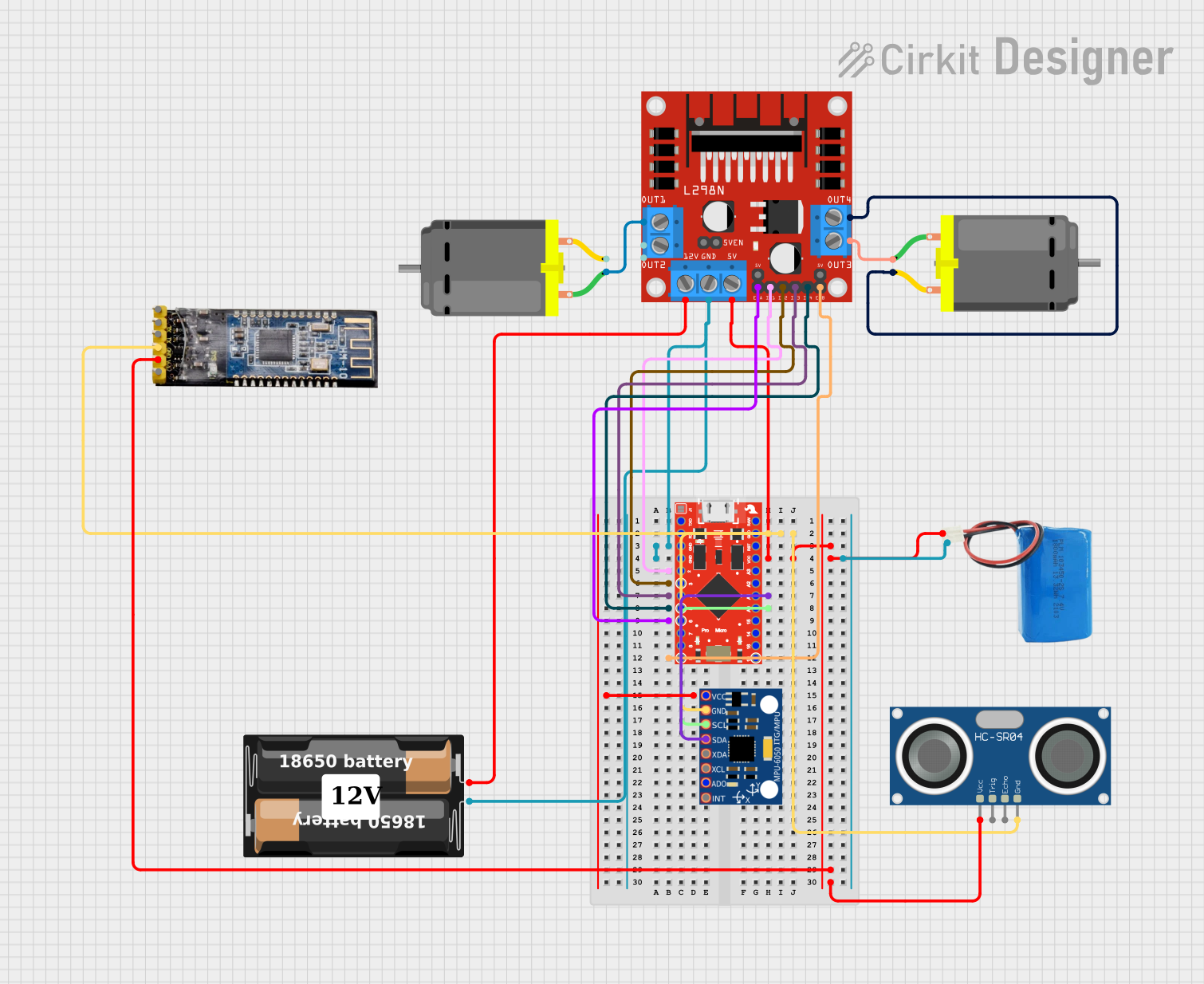
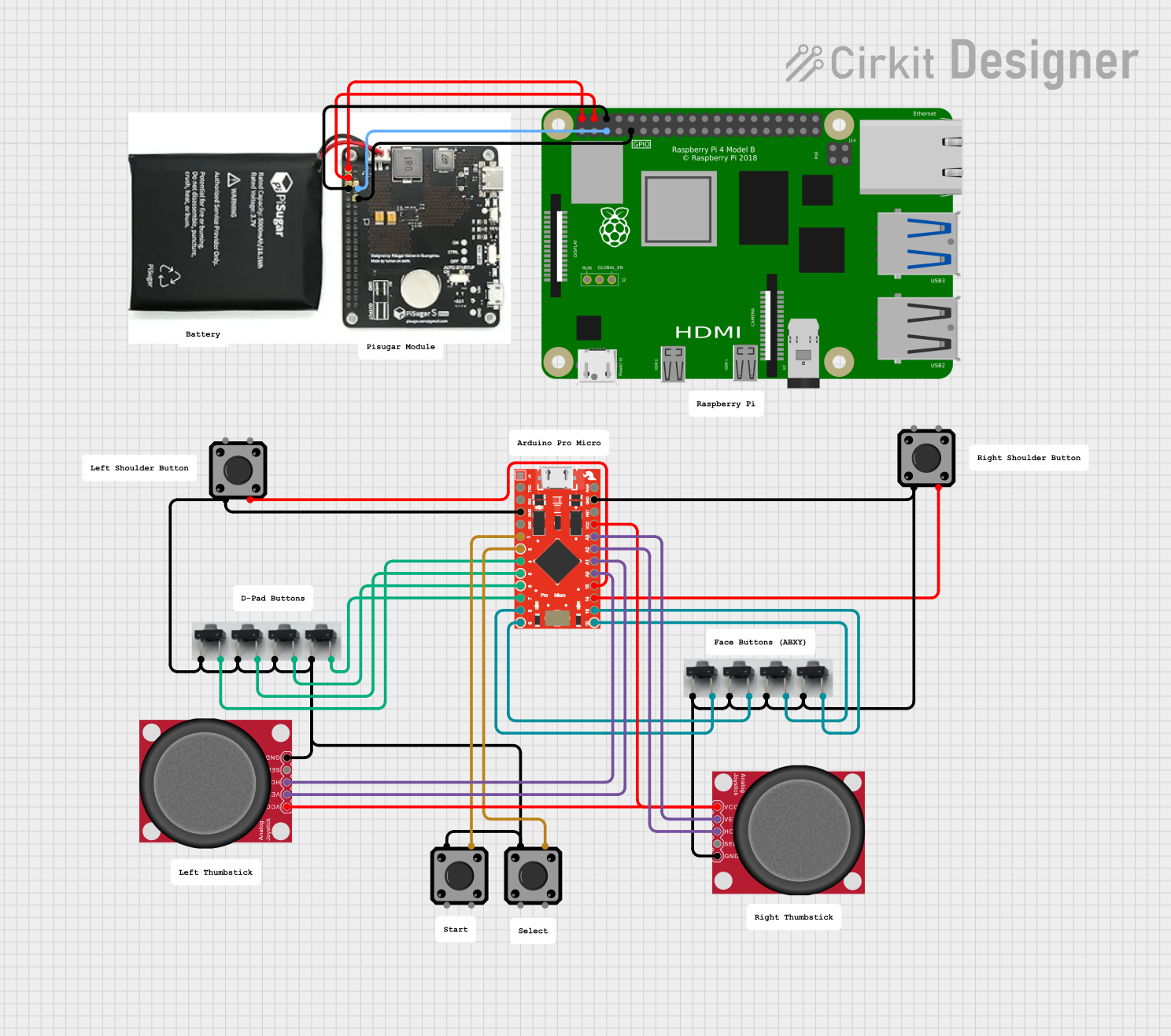

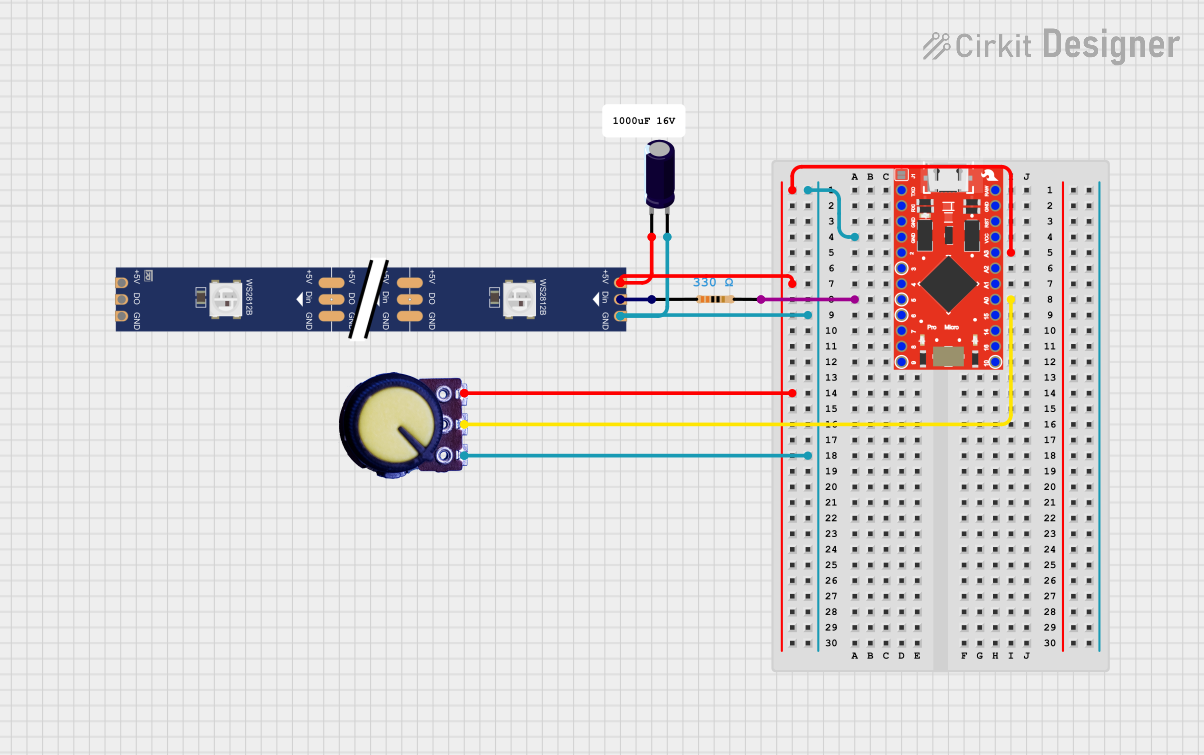
Explore Projects Built with SparkFun Pro Micro
Common Applications and Use Cases
- Wearable electronics
- USB Human Interface Device (HID) projects
- Compact embedded systems
- Prototyping IoT devices
- Robotics
Technical Specifications
Key Technical Details
- Microcontroller: ATmega32U4
- Operating Voltage: 5V or 3.3V (depending on the model)
- Input Voltage: 4-9V (5V model) or 3.3-12V (3.3V model)
- Digital I/O Pins: 12 (of which 5 can be used as PWM outputs)
- Analog Input Pins: 4
- Clock Speed: 16 MHz (5V model) or 8 MHz (3.3V model)
- Flash Memory: 32 KB (ATmega32U4) of which 4 KB used by bootloader
- SRAM: 2.5 KB (ATmega32U4)
- EEPROM: 1 KB (ATmega32U4)
- USB Connectivity: Built-in micro USB port for programming and serial communication
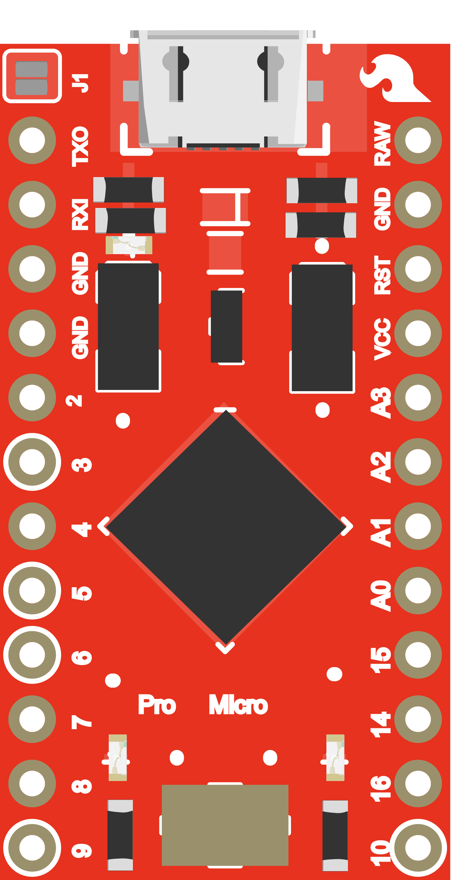
Pin Configuration and Descriptions
| Pin Number | Function | Description |
|---|---|---|
| 1 | GND | Ground |
| 2 | RST | Reset pin, active low |
| 3 | VCC | Positive supply voltage |
| 4-5 | PD5, PD6 | Digital pins, PWM capable (D3, D4) |
| 6-7 | PD7, PE6 | Digital pins (D6, D7) |
| 8-11 | PB0-PB3 | Digital pins, PWM capable (D8-D10), MOSI/MISO |
| 12 | PB4 | Digital pin, PWM capable (D11), MISO |
| 13-16 | PB5-PB7, PD0 | Digital pins (D14-D16), SCK, RX LED |
| 17-20 | PD1-PD4 | Digital pins (D2, D5, TX LED, RX) |
| 21-24 | PF0-PF3 | Analog pins (A1-A4) |
| 25 | PF4 | Analog pin (A5) |
Usage Instructions
How to Use the Component in a Circuit
Powering the Pro Micro: Connect the VCC pin to a 5V or 3.3V power supply, depending on the model of your Pro Micro. Ensure that the power supply is within the input voltage range specified for your model.
Programming the Pro Micro: Connect the board to your computer using a micro USB cable. The Pro Micro can be programmed using the Arduino IDE. Select "Arduino Leonardo" as the board type, as the Pro Micro shares the same microcontroller.
Connecting I/O Pins: Use the digital and analog pins to connect sensors, actuators, and other components. Remember to configure the pins correctly in your code.
Using USB Functionality: To use the Pro Micro's USB capabilities, include the appropriate libraries in your Arduino sketch, such as
Keyboard.horMouse.h.
Important Considerations and Best Practices
- Always ensure that the power supply voltage matches the requirements of the Pro Micro model you are using.
- When using the USB functionality, be aware that the Pro Micro will register as a USB device on the connected computer.
- Avoid connecting high-current loads directly to the I/O pins to prevent damage to the microcontroller.
- Use a current-limiting resistor when connecting LEDs to the I/O pins.
Troubleshooting and FAQs
Common Issues Users Might Face
- Pro Micro not recognized by computer: Ensure that the micro USB cable is properly connected and that the cable supports data transfer, not just charging.
- Sketch upload fails: Double-check the board and port selections in the Arduino IDE. Press the reset button on the Pro Micro twice quickly to enter bootloader mode if necessary.
- I/O pin not functioning: Verify that the pin is configured correctly in your sketch and that there are no shorts or open circuits in your connections.
Solutions and Tips for Troubleshooting
- If the Pro Micro is not recognized, try using a different USB port or cable.
- Ensure that the correct drivers are installed for the Pro Micro on your computer.
- Use serial print statements to debug your code and verify that the program is running as expected.
Example Code for Arduino UNO
Here is a simple example of how to blink an LED connected to pin 9 (D9) on the SparkFun Pro Micro:
// Define the LED pin
const int ledPin = 9;

void setup() {
  // Set the LED pin as an output
  pinMode(ledPin, OUTPUT);
}

void loop() {
  // Turn the LED on
  digitalWrite(ledPin, HIGH);
  delay(1000); // Wait for 1 second
  // Turn the LED off
  digitalWrite(ledPin, LOW);
  delay(1000); // Wait for 1 second
}
Remember to adjust the ledPin variable if you connect your LED to a different pin. This code will toggle the LED on and off every second, creating a blinking effect.