How to Use Interface Terminal Block: Examples, Pinouts, and Specs
Introduction
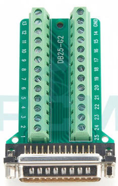
The PCM DB25-G Interface Terminal Block is a versatile and reliable device designed to connect and secure electrical wires. It provides a convenient way to establish safe and organized connections between different parts of a circuit. This terminal block is particularly useful in applications requiring quick wiring changes, secure connections, and easy troubleshooting.
Explore Projects Built with Interface Terminal Block


Explore Projects Built with Interface Terminal Block
Common Applications and Use Cases
- Industrial control systems
- Prototyping and testing of circuits
- Signal distribution in automation systems
- Interfacing with DB25 connectors for communication or data transfer
- Laboratory setups for quick and secure wiring
Technical Specifications
The following table outlines the key technical details of the PCM DB25-G Interface Terminal Block:
| Parameter | Value |
|---|---|
| Manufacturer | PCM |
| Part ID | DB25-G |
| Connector Type | DB25 Female |
| Number of Terminals | 25 |
| Wire Size Compatibility | 26–16 AWG |
| Voltage Rating | 300V AC/DC |
| Current Rating | 10A |
| Mounting Type | DIN Rail or Panel Mount |
| Material | Flame-retardant plastic housing |
| Operating Temperature | -40°C to 85°C |
Pin Configuration and Descriptions
The DB25-G terminal block is designed to interface with a standard DB25 connector. The pinout corresponds to the standard DB25 pin numbering, as shown below:
| DB25 Pin | Terminal Block Pin | Description |
|---|---|---|
| 1 | 1 | Signal/Power Line 1 |
| 2 | 2 | Signal/Power Line 2 |
| 3 | 3 | Signal/Power Line 3 |
| ... | ... | ... |
| 25 | 25 | Signal/Power Line 25 |
Note: The terminal block provides a 1:1 mapping between the DB25 connector pins and the screw terminals, ensuring straightforward wiring.
Usage Instructions
How to Use the Component in a Circuit
Mounting the Terminal Block:
- Secure the terminal block to a DIN rail or panel using the provided mounting slots.
- Ensure the terminal block is firmly attached to prevent movement during operation.
Connecting Wires:
- Strip the insulation from the wire ends (approximately 5–7 mm).
- Insert the stripped wire into the appropriate screw terminal.
- Tighten the screw to secure the wire. Avoid overtightening to prevent damage to the wire or terminal.
Interfacing with a DB25 Connector:
- Plug the DB25 connector into the female port on the terminal block.
- Ensure the connector is fully seated and locked in place.
Testing the Connections:
- Use a multimeter to verify continuity between the DB25 pins and the corresponding screw terminals.
- Check for any loose connections or short circuits before powering the circuit.
Important Considerations and Best Practices
- Wire Selection: Use wires within the supported range (26–16 AWG) to ensure proper fit and electrical performance.
- Tightening Screws: Do not overtighten the screws, as this may damage the terminal block or the wires.
- Environmental Conditions: Ensure the terminal block is used within its operating temperature range (-40°C to 85°C).
- Labeling: Clearly label the wires and terminals to simplify troubleshooting and future modifications.
Example: Connecting to an Arduino UNO
The DB25-G terminal block can be used to interface an Arduino UNO with external devices. Below is an example of connecting a DB25 terminal block to an Arduino for controlling LEDs:
Circuit Setup
- Connect the DB25 terminal block to the Arduino using jumper wires.
- Use the terminal block to distribute signals to LEDs connected to pins 2, 3, and 4 of the Arduino.
Arduino Code
// Example code to control LEDs connected via the DB25 terminal block

// Define LED pins
const int ledPin1 = 2; // LED connected to DB25 pin 2
const int ledPin2 = 3; // LED connected to DB25 pin 3
const int ledPin3 = 4; // LED connected to DB25 pin 4

void setup() {
  // Set LED pins as outputs
  pinMode(ledPin1, OUTPUT);
  pinMode(ledPin2, OUTPUT);
  pinMode(ledPin3, OUTPUT);
}

void loop() {
  // Turn LEDs on and off in sequence
  digitalWrite(ledPin1, HIGH); // Turn on LED 1
  delay(500);                  // Wait for 500ms
  digitalWrite(ledPin1, LOW);  // Turn off LED 1

  digitalWrite(ledPin2, HIGH); // Turn on LED 2
  delay(500);                  // Wait for 500ms
  digitalWrite(ledPin2, LOW);  // Turn off LED 2

  digitalWrite(ledPin3, HIGH); // Turn on LED 3
  delay(500);                  // Wait for 500ms
  digitalWrite(ledPin3, LOW);  // Turn off LED 3
}
Troubleshooting and FAQs
Common Issues and Solutions
Loose Connections:
- Issue: Wires are not securely connected to the terminal block.
- Solution: Ensure the screws are tightened properly and the wires are stripped to the correct length.
No Signal Transmission:
- Issue: Signal is not passing through the terminal block.
- Solution: Check for continuity between the DB25 connector pins and the corresponding screw terminals using a multimeter.
Overheating:
- Issue: Terminal block becomes hot during operation.
- Solution: Verify that the current does not exceed the 10A rating. Use thicker wires if necessary.
DB25 Connector Not Fitting:
- Issue: The DB25 connector does not fit into the terminal block.
- Solution: Ensure the connector is aligned correctly and free of debris.
FAQs
Q: Can the DB25-G terminal block be used for high-frequency signals?
A: Yes, but ensure proper shielding and grounding to minimize interference.Q: Is the terminal block compatible with male DB25 connectors?
A: No, the DB25-G is designed for female DB25 connectors only.Q: Can I use this terminal block for power distribution?
A: Yes, as long as the voltage and current ratings are not exceeded.Q: How do I clean the terminal block?
A: Use a dry cloth or compressed air to remove dust. Avoid using liquids or solvents.