How to Use ZMPT101B: Examples, Pinouts, and Specs
Introduction
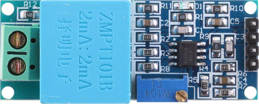
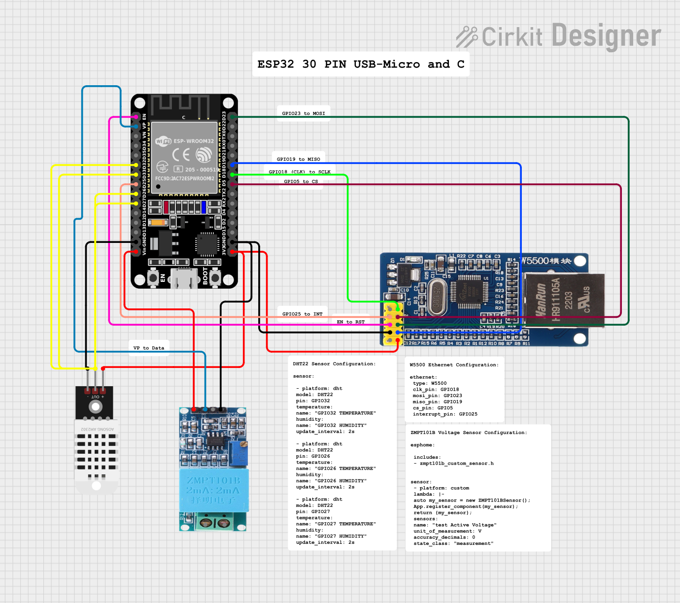
The ZMPT101B is a high-precision voltage sensor module designed for electronic applications that require accurate AC voltage measurements. This module is based on the ZMPT101B voltage transformer and uses a high-precision op-amp circuit to amplify the signal for microcontroller compatibility. It is commonly used in power monitoring systems, voltage regulation, and for DIY projects that involve AC voltage sensing, such as home energy management systems.
Explore Projects Built with ZMPT101B
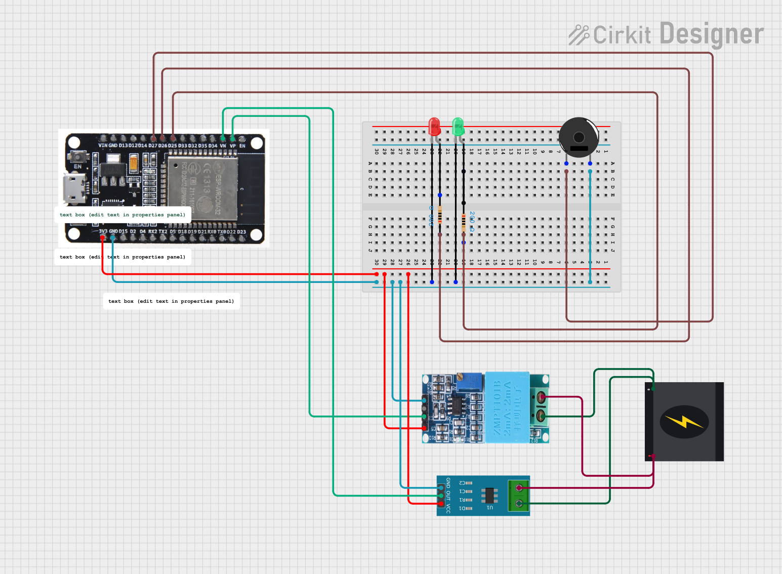
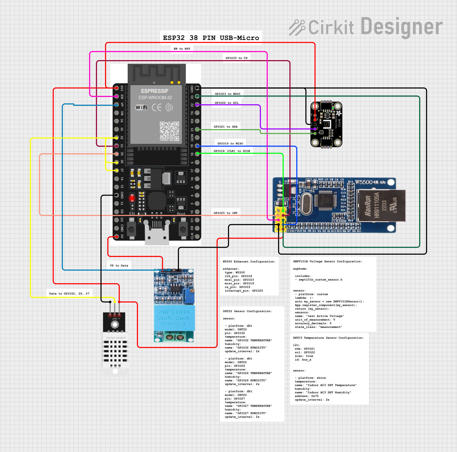
Explore Projects Built with ZMPT101B
Technical Specifications
Key Technical Details
- Voltage Sensing Range: 0-250V AC (primary voltage)
- Linear Range: 0-2V AC (output voltage)
- Precision: 1%
- Supply Voltage: 5V-30V DC
- Frequency Range: 50Hz-60Hz
- Phase Shift: < 5°
- Operating Temperature: -40°C to +70°C
Pin Configuration and Descriptions
| Pin Number | Pin Name | Description |
|---|---|---|
| 1 | VCC | Power supply (5V-30V DC) |
| 2 | GND | Ground |
| 3 | OUT | Analog voltage output proportional to AC |
Usage Instructions
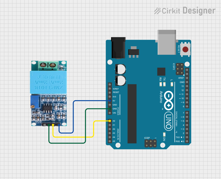
Integration with a Circuit
To use the ZMPT101B module in a circuit, follow these steps:
- Connect the VCC pin to a DC power supply within the 5V-30V range.
- Connect the GND pin to the common ground in your circuit.
- Connect the OUT pin to an analog input on your microcontroller, such as an Arduino.
Calibration
Before using the ZMPT101B for precise measurements, it is essential to calibrate the module:
- Apply a known AC voltage to the input and measure the output voltage.
- Adjust the onboard potentiometer until the module's output matches the expected value.
- Record the calibration factor for use in your code.
Best Practices
- Ensure that the AC voltage does not exceed the module's maximum rating to avoid damage.
- Use a proper filter if the AC signal is noisy to improve measurement accuracy.
- Avoid placing the module near high-power equipment to prevent electromagnetic interference.
Example Code for Arduino UNO
// ZMPT101B voltage sensor example for Arduino UNO
const int zmptPin = A0; // Analog input pin connected to ZMPT101B OUT
float calibrationFactor = 0.5; // Replace with your calibration factor

void setup() {
  Serial.begin(9600);
}

void loop() {
  int sensorValue = analogRead(zmptPin);
  float voltage = sensorValue * (5.0 / 1023.0) * calibrationFactor;
  Serial.print("AC Voltage: ");
  Serial.print(voltage);
  Serial.println(" V");
  delay(1000);
}
Troubleshooting and FAQs
Common Issues
- Inaccurate Readings: Ensure the module is calibrated correctly. Adjust the onboard potentiometer if necessary.
- No Output: Check the power supply and wiring. Ensure the VCC and GND are correctly connected.
- Signal Noise: Implement a low-pass filter or move the module away from high-power devices.
FAQs
Q: Can the ZMPT101B be used for DC voltage measurements? A: No, the ZMPT101B is designed for AC voltage measurements only.
Q: What is the purpose of the onboard potentiometer? A: The potentiometer is used for calibration to ensure accurate voltage measurements.
Q: How can I increase the measurement resolution? A: Use an external ADC with higher resolution or implement oversampling with the Arduino's ADC.
For further assistance, consult the community forums or contact technical support.