Cirkit Designer Logo
Cirkit Designer
Your all-in-one circuit design IDE
Home / 
Component Documentation

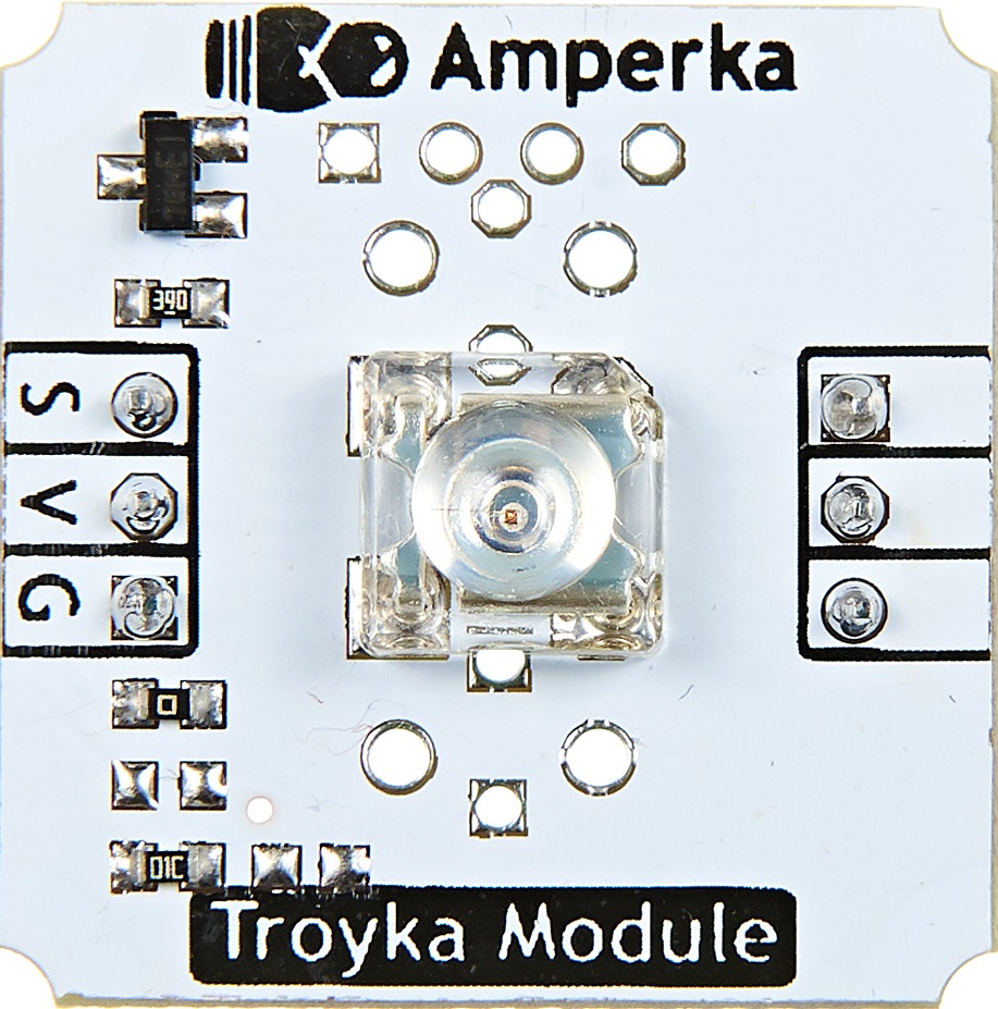
How to Use troyka_LED_White: Examples, Pinouts, and Specs

Image of troyka_LED_White
Cirkit Designer LogoDesign with troyka_LED_White in Cirkit Designer

Introduction

The Troyka White LED module is a compact and easy-to-use electronic component that emits white light when an electrical current passes through it. LEDs are widely used in various applications due to their low power consumption, long life, and compact size. Common applications for the Troyka White LED include indicator lights, backlighting, decorative lighting, and DIY electronics projects. This module is particularly suitable for educational purposes, hobbyist projects, and prototyping.

Explore Projects Built with troyka_LED_White

Use Cirkit Designer to design, explore, and prototype these projects online. Some projects support real-time simulation. Click "Open Project" to start designing instantly!
Battery-Powered LED Toggle Switch Circuit
Image of EXP. 7 E: A project utilizing troyka_LED_White in a practical application
This circuit consists of a red LED, a toggle switch, and a power source. The LED is powered by a 3.7V supply from the MAHIR 1.mini module, and its illumination is controlled by the toggle switch, which connects or disconnects the LED's cathode to ground.
Cirkit Designer LogoOpen Project in Cirkit Designer
Battery-Powered LED Strip with Toggle Switch and Fuse Protection
Image of wern: A project utilizing troyka_LED_White in a practical application
This circuit is a simple 12V lighting system that uses a toggle switch to control a 12V white LED strip. The circuit includes a fuse for overcurrent protection and is powered by a 12V battery.
Cirkit Designer LogoOpen Project in Cirkit Designer
Battery-Powered RGB LED Control with Pushbuttons
Image of EXP-12 E: A project utilizing troyka_LED_White in a practical application
This circuit consists of an RGB LED controlled by three pushbuttons, each corresponding to one of the LED's color channels (Red, Green, and Blue). The pushbuttons are powered by a MAHIR 1.mini power source, allowing the user to manually toggle each color channel of the RGB LED.
Cirkit Designer LogoOpen Project in Cirkit Designer
Arduino MKR WiFi 1010 IR Remote-Controlled LED
Image of last lab: A project utilizing troyka_LED_White in a practical application
This circuit uses an Arduino MKR WiFi 1010 to control a white LED based on input from a VS1838B IR receiver. The Arduino reads signals from an IR remote and turns the LED on or off depending on the received command.
Cirkit Designer LogoOpen Project in Cirkit Designer

Explore Projects Built with troyka_LED_White

Use Cirkit Designer to design, explore, and prototype these projects online. Some projects support real-time simulation. Click "Open Project" to start designing instantly!
Image of EXP. 7 E: A project utilizing troyka_LED_White in a practical application
Battery-Powered LED Toggle Switch Circuit
This circuit consists of a red LED, a toggle switch, and a power source. The LED is powered by a 3.7V supply from the MAHIR 1.mini module, and its illumination is controlled by the toggle switch, which connects or disconnects the LED's cathode to ground.
Cirkit Designer LogoOpen Project in Cirkit Designer
Image of wern: A project utilizing troyka_LED_White in a practical application
Battery-Powered LED Strip with Toggle Switch and Fuse Protection
This circuit is a simple 12V lighting system that uses a toggle switch to control a 12V white LED strip. The circuit includes a fuse for overcurrent protection and is powered by a 12V battery.
Cirkit Designer LogoOpen Project in Cirkit Designer
Image of EXP-12 E: A project utilizing troyka_LED_White in a practical application
Battery-Powered RGB LED Control with Pushbuttons
This circuit consists of an RGB LED controlled by three pushbuttons, each corresponding to one of the LED's color channels (Red, Green, and Blue). The pushbuttons are powered by a MAHIR 1.mini power source, allowing the user to manually toggle each color channel of the RGB LED.
Cirkit Designer LogoOpen Project in Cirkit Designer
Image of last lab: A project utilizing troyka_LED_White in a practical application
Arduino MKR WiFi 1010 IR Remote-Controlled LED
This circuit uses an Arduino MKR WiFi 1010 to control a white LED based on input from a VS1838B IR receiver. The Arduino reads signals from an IR remote and turns the LED on or off depending on the received command.
Cirkit Designer LogoOpen Project in Cirkit Designer

Technical Specifications

Key Technical Details

  • Forward Voltage (Typical): 3.3V to 5V
  • Forward Current (Typical): 20mA
  • Luminous Intensity: Dependent on current and temperature
  • Viewing Angle: Approximately 120 degrees
  • Operating Temperature: -25°C to 85°C

Pin Configuration and Descriptions

Pin Number Description Notes
1 Anode (+) Connect to positive voltage
2 Cathode (-) Connect to ground (GND)

Usage Instructions

How to Use the Component in a Circuit

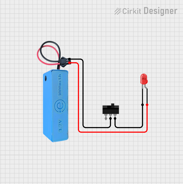
  1. Power Supply: Ensure that the power supply voltage does not exceed the maximum forward voltage of the LED. Use a current-limiting resistor to prevent damage to the LED.

  2. Current-Limiting Resistor: Calculate the value of the current-limiting resistor using Ohm's law: R = (V_supply - V_forward) / I_forward. For a 5V supply and a typical forward current of 20mA, the resistor value would be (5V - 3.3V) / 0.02A = 85Ω. Choose the nearest standard resistor value, which is 82Ω.

  3. Connection: Connect the anode of the LED to the positive side of the power supply through the current-limiting resistor. Connect the cathode to the ground (GND).

Important Considerations and Best Practices

  • Polarity: LEDs are polarized components. Ensure correct polarity by connecting the anode and cathode to the appropriate terminals.
  • Heat Dissipation: Although LEDs are efficient, they can still generate heat. Ensure adequate ventilation around the LED.
  • Overcurrent Protection: Always use a current-limiting resistor to protect the LED from overcurrent conditions.

Example Code for Arduino UNO

// Define the pin connected to the LED
const int ledPin = 13; // Most Arduino UNOs have an onboard LED on pin 13

void setup() {
  // Set the LED pin as an output
  pinMode(ledPin, OUTPUT);
}

void loop() {
  // Turn the LED on
  digitalWrite(ledPin, HIGH);
  delay(1000); // Wait for 1 second
  // Turn the LED off
  digitalWrite(ledPin, LOW);
  delay(1000); // Wait for 1 second
}

Troubleshooting and FAQs

Common Issues

  • LED Not Lighting Up: Check the polarity of the connections. Ensure the anode is connected to the positive voltage and the cathode to GND.
  • LED Too Dim: Confirm that the current-limiting resistor is the correct value. A resistor value that's too high can result in a dim LED.
  • LED Burnt Out: A burnt-out LED may be due to excessive current. Ensure that the power supply voltage and current-limiting resistor are appropriate.

Solutions and Tips for Troubleshooting

  • Double-Check Connections: Verify that all connections are secure and correctly polarized.
  • Resistor Value: Recalculate the resistor value if the LED brightness is not as expected.
  • Power Supply: Use a multimeter to confirm that the power supply is delivering the correct voltage.

FAQs

Q: Can I connect the LED directly to a 5V power supply? A: No, you should always use a current-limiting resistor to prevent damage to the LED.

Q: What happens if I reverse the polarity of the LED? A: The LED will not light up if the polarity is reversed, and prolonged reverse connection may damage the LED.

Q: How do I know if my LED is burnt out? A: A burnt-out LED will not emit light even with the correct power supply and polarity. Use a multimeter to check for continuity across the LED pins. If there is no continuity, the LED is likely burnt out.